
The Thermal Mass Problem: Why Factory Calibration Fails on Speaker Wire
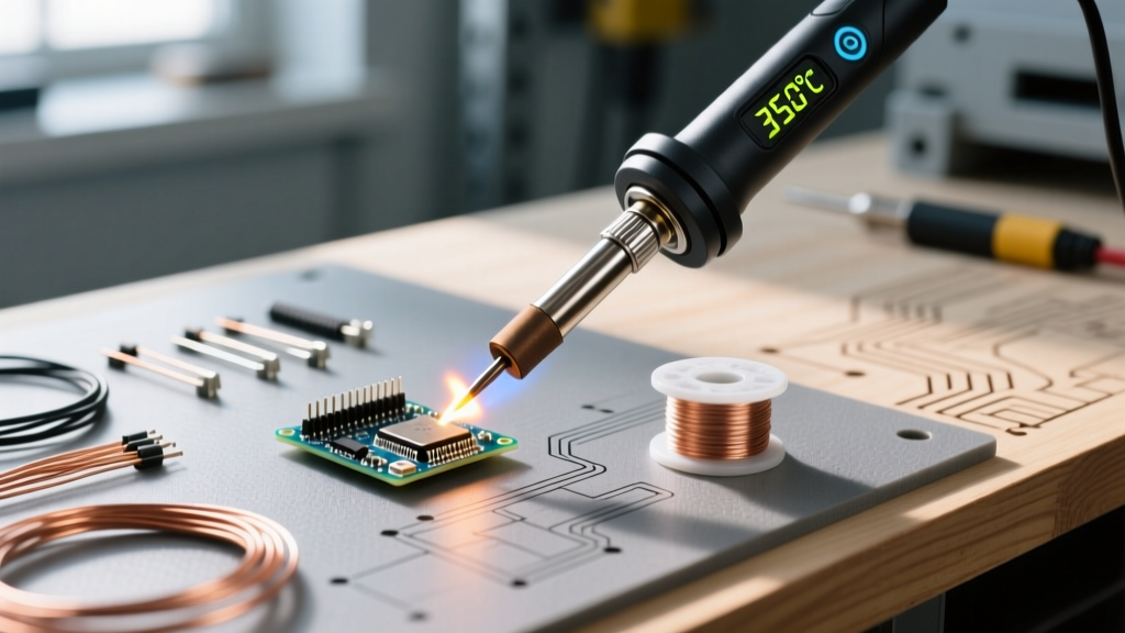
Soldering 12 AWG to 14 AWG speaker wire is fundamentally different from soldering PCB traces or 22 AWG jumper wires. Copper possesses a thermal conductivity of approximately 400 W/(m·K). When you apply a standard soldering iron tip to a thick stranded copper bundle, the wire acts as a massive heatsink, instantly pulling thermal energy away from the tip. A factory-calibrated iron set to 350°C (662°F) can experience a localized tip temperature drop to below 200°C upon contact, resulting in a classic 'cold joint' characterized by a dull, grainy appearance and high electrical resistance.
To achieve reliable, low-resistance audio connections, you must move beyond default settings. This guide covers the exact setup, calibration, and thermal offset protocols required for high-gauge speaker wire in 2026, utilizing industry-standard bench stations and modern portable smart irons.
Hardware Selection: Thermal Recovery is King
Before calibrating, ensure your hardware can sustain the thermal load. Wattage dictates how fast the heater can replenish lost heat, while tip mass dictates how much heat is stored at the point of contact.
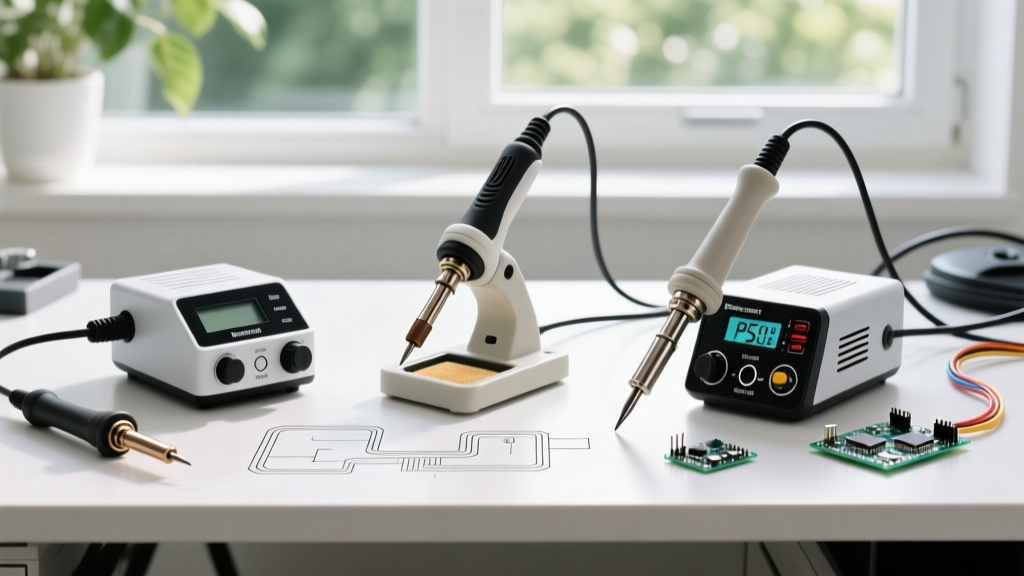
- Hakko FX-888D (Bench Standard): Priced around $115 in 2026, this 70W station remains the gold standard for bench work. Its analog-to-digital thermal feedback loop is highly responsive, but it requires manual offset calibration for heavy-duty tips.
- Pinecil V2 (Portable Smart Iron): Costing roughly $35 (plus power supply), this RISC-V powered iron relies on USB-C Power Delivery (PD). For 12 AWG speaker wire, you must pair it with a 100W PD 3.1 GaN charger. A standard 65W laptop charger will bottleneck the iron's thermal recovery during heavy draws.
- Weller WE1010NA: A solid 70W alternative (~$110) featuring a high-mass ETA tip series, excellent for continuous speaker wire termination in custom AV installations.
Step-by-Step Calibration: Hakko FX-888D Offset Protocol
The internal thermocouple in the Hakko FX-888D measures the temperature of the ceramic heater, not the extreme end of the tip. Heavy-duty tips like the T18-D52 (5.2mm Chisel) or T18-K (Knife) have a different thermal gradient than the standard T18-B (Conical) tip the station was calibrated with at the factory. You must recalibrate the digital offset with your high-mass tip installed.
The Calibration Sequence
- Preparation: Install your chosen high-mass tip (e.g., T18-D52). Turn the station OFF. Have a reliable digital tip thermometer (like the Hakko FG-100) ready.
- Enter Calibration Mode: Press and hold the UP arrow button on the front panel. While holding it, turn the power switch ON. Release the UP button when the digital display reads 'CAL'.
- Measure and Adjust: Press the ENTER button. The display will show the current offset temperature. Place your tip thermometer probe directly on the flat face of the chisel tip. Wait 10 seconds for the reading to stabilize.
- Input the Delta: If your thermometer reads 365°C but the station is set to 380°C, use the UP/DOWN arrows to adjust the station's internal offset value until it matches your physical thermometer reading.
- Save and Lock: Press ENTER to save the new offset. The station will return to normal heating mode, now perfectly calibrated for the specific thermal mass of your speaker wire tip.
Smart Iron Setup: Pinecil V2 Power Negotiation
Unlike analog stations, the Pinecil V2 handles calibration digitally via its firmware, but 'calibration' in this context means configuring the power delivery and boost parameters to compensate for the speaker wire's heatsink effect.
According to the Pinecil V2 documentation, the iron will only negotiate maximum wattage if the connected USB-C cable supports 5A (100W) or 3A (60W) PD profiles. Using a standard 3A cable with a 100W brick will artificially cap your thermal recovery at 60W.
Optimal Firmware Settings for 12-14 AWG
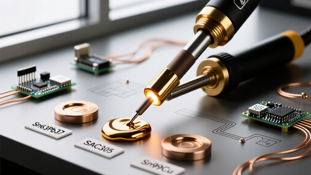
- Base Temperature: 380°C (716°F) for Sn63Pb37 (63/37 Leaded) solder.
- Boost Temperature: 420°C (788°F). Map this to the '+' button or automatic motion-detection.
- PD Timeout: Set to 2 seconds to ensure rapid power negotiation upon boot.
- Tip Selection in Firmware: Select the 'Pine64 Long' or 'TS100' profile depending on your exact tip insert, ensuring the PID algorithm uses the correct thermal mass curve.
Tip Geometry & Thermal Transfer Matrix
Selecting the correct tip geometry is just as critical as temperature calibration. According to the IPC J-STD-001 standard for soldered electrical assemblies, maximum surface area contact is required to ensure rapid heat transfer and complete wetting without lingering and damaging wire insulation.
| Wire Gauge (AWG) | Recommended Tip Geometry | Hakko Tip Model | Target Temp (Sn63) | Max Dwell Time |
|---|---|---|---|---|
| 10 - 12 AWG | Heavy Chisel or Wide Bevel | T18-D52 or T18-K | 380°C - 390°C | 4.0 Seconds |
| 14 AWG | Standard Chisel (3.2mm) | T18-D32 | 360°C - 370°C | 3.0 Seconds |
| 16 AWG | Narrow Chisel (2.4mm) | T18-D24 | 340°C - 350°C | 2.5 Seconds |
Note: If using lead-free SAC305 alloy, add 20°C to all target temperatures and increase dwell time by 0.5 seconds.
The Pre-Tinning Execution Protocol
Even a perfectly calibrated iron will fail if the physical execution is flawed. Speaker wire strands oxidize rapidly when exposed to high heat. Follow this exact sequence for every connection:
- Strip and Twist: Strip exactly 1/2 inch of insulation. Tightly twist the stranded copper to eliminate air gaps, which act as thermal insulators.
- Apply Liquid or Gel Flux: Do not rely solely on rosin-core solder. Apply a small drop of tacky flux (e.g., Amtech NC-559 or MG Chemicals 8341) to the bare wire. This lowers the surface tension and prevents oxidation during the pre-tinning phase.
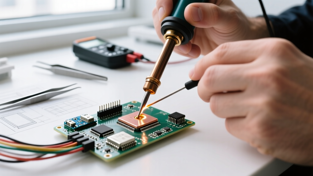
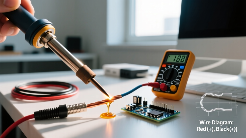
- Pre-Tin the Wire: Apply the calibrated tip to the wire, then feed 0.062-inch diameter solder (like Kester 44) into the joint, not just the tip. The wire should wick the solder instantly. A properly tinned 12 AWG wire will look shiny and metallic, with no bulky solder blobs on the outside.
- Pre-Tin the Terminal: Apply the same process to the speaker binding post or spade/lug connector.
- The Final Marriage: Bring the two pre-tinned surfaces together. Apply the iron for exactly 1.5 to 2 seconds. The existing solder on both surfaces will reflow and merge into a single, continuous metallurgical bond.
When selecting wire gauges for high-current audio runs, resources like the Crutchfield speaker wire guide recommend 12 AWG for runs exceeding 50 feet to prevent signal degradation. Properly soldering these thicker runs requires strict adherence to the thermal protocols outlined above.
Common Failure Modes & Troubleshooting
Graping (Rough, Matte Surface)
Cause: Flux burnout. If your iron is calibrated too high (above 400°C for leaded solder) or your dwell time exceeds 5 seconds, the rosin flux vaporizes completely, leaving the molten solder exposed to oxygen. It oxidizes instantly, creating a rough, grape-like texture.
Fix: Lower your base temperature by 10°C, apply fresh liquid flux, and reflow with a pre-tinned tip.
De-Wetting (Solder Balls Up and Refuses to Stick)
Cause: Severe oxidation on the copper wire or a degraded iron tip. If the wire was stripped and left exposed to air for days before soldering, a thick layer of copper oxide has formed.
Fix: Mechanically clean the wire with a fiberglass scratch pen or fine sandpaper before applying flux. If the iron tip is de-wetting, it has suffered from 'tip blackening.' Clean it using a brass wire sponge (never a wet cellulose sponge, which causes thermal shock and micro-fractures in the iron plating).
Cold Joint Cracking
Cause: Movement during the cooling phase. Because 12 AWG wire is stiff, if the wire shifts while the solder is transitioning from liquid to solid (the plastic state), the internal crystalline structure fractures.
Fix: Use a 'third hand' tool or hemostats to clamp the wire rigidly to the terminal. Do not blow on the joint to cool it; allow it to air-cool naturally for 3 seconds.
Final Thoughts on Audio Integrity
Calibrating your soldering iron for speaker wire is not about achieving the highest possible temperature; it is about matching your tool's thermal recovery rate to the specific mass of the copper you are working with. By adjusting your digital offsets, utilizing high-mass chisel tips, and strictly controlling your flux chemistry, you will create terminations that offer zero measurable resistance and will outlast the speakers themselves.