
The Physics of Thermal Transfer: Beyond the Display
One of the most common misconceptions in electronics assembly is equating the digital readout on a soldering station with the actual heat energy transferred to a joint. As of 2026, modern PID-controlled stations like the Pinecil V2 or the Weller WE1010NA can display a target temperature with near-instantaneous algorithmic corrections. However, the soldering iron tip temperature range required to successfully flow solder depends not just on the thermal degree, but on the thermal mass and contact area of the tip geometry.
Temperature is merely a measure of average kinetic energy, while heat is the transfer of thermal energy (measured in Joules). A narrow conical tip set to 400°C may fail to melt solder on a multilayer PCB ground plane, while a wide chisel tip set to 320°C will flow it effortlessly. Understanding this distinction is the first step in troubleshooting cold joints, lifted pads, and thermal damage to sensitive ICs.
Optimal Soldering Iron Tip Temperature Range by Alloy
Selecting the correct baseline temperature is critical. Exceeding the necessary range accelerates tip oxidation and degrades the flux core, while falling short causes prolonged dwell times that wick heat into component bodies. Below is the definitive reference matrix for standard electronics alloys.
| Alloy Composition | Melting Point | Ideal Tip Temperature Range | Max Dwell Time | Common Application |
|---|---|---|---|---|
| Sn63/Pb37 (Leaded) | 183°C (361°F) | 300°C - 330°C | 2-3 seconds | Prototyping, vintage repair |
| SAC305 (Lead-Free) | 217°C - 220°C | 330°C - 360°C | 2-4 seconds | Commercial SMT/THT assembly |
| Sn99.3/Cu0.7 | 227°C (441°F) | 340°C - 370°C | 3-5 seconds | High-reliability plumbing/wiring |
| Sn42/Bi57.6/Ag0.4 | 138°C (280°F) | 220°C - 250°C | 1-2 seconds | Low-temp, heat-sensitive flex |
Note: Always consult the IPC J-STD-001 Standards for specific Class 1, 2, and 3 reliability requirements regarding thermal profiling and maximum allowable dwell times.
Troubleshooting: When Your Station Fails to Hit the Target Range
If your station reads 350°C but the solder remains stubbornly solid, do not immediately crank the dial to 450°C. This is a symptom of thermal resistance, not necessarily a broken heating element. Here is how to diagnose the failure mode.
1. The Oxidation Insulation Layer
Iron-plated copper tips oxidize rapidly when left at high temperatures without a protective layer of solder. This oxidation layer acts as a severe thermal insulator. A heavily oxidized tip can lose up to 85% of its thermal transfer efficiency. If the tip appears black or crusty, the sensor inside the heater is reading the correct temperature, but the working surface of the tip is hundreds of degrees cooler.
- The Fix: Never use a steel file or sandpaper. Use a chemical tip tinner (e.g., MG Chemicals 4901, approx. $14) which contains mild acids and solder powder to strip oxidation and re-tin the surface simultaneously.
2. Sensor and Heating Element Degradation
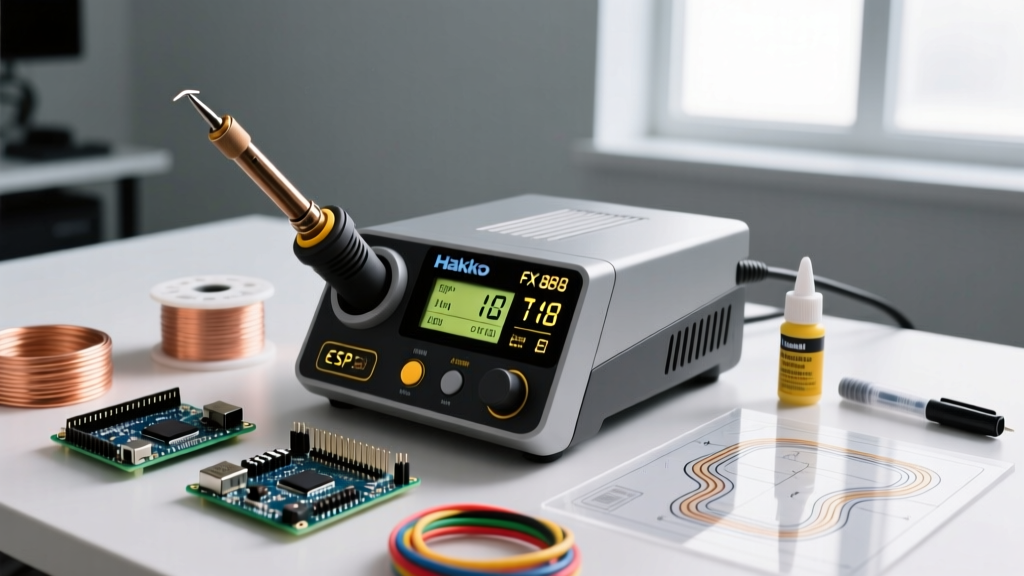
In stations where the thermocouple is separate from the heater (like the classic Hakko FX-888D, ~$115), physical shock or repeated thermal expansion can cause the sensor wire to fracture or lose contact with the inner tip wall.
- Hakko Error Code 'H-E': Indicates a broken sensor or heater circuit. Check the 5-pin connector at the base of the handpiece for bent pins.
- Weller Error Code 'E03': Indicates an open circuit in the sensor. Often resolved by replacing the WSP80 heating element.
3. Thermal Mass Mismatch
Attempting to solder a 10 AWG wire or a large copper pour using a 1mm conical tip will result in a cold joint, regardless of the soldering iron tip temperature range you select. The tip simply lacks the physical mass to sustain heat transfer into the high-thermal-conductivity workpiece.
Expert Insight: When working with heavy ground planes, switch to a bevel or wide chisel tip to maximize surface area contact. If the joint still won't flow, introduce localized preheating (using a hot air gun set to 120°C) to raise the ambient baseline of the PCB, rather than maxing out your iron's temperature.
Maintenance Protocols to Preserve Temperature Accuracy
Maintaining the integrity of your tip ensures that the temperature displayed on your station matches the physical reality at the work surface. The Hakko USA Official Tip Care Guidelines emphasize that improper cleaning is the leading cause of premature tip failure.
The Wet Sponge vs. Brass Wool Debate
For decades, the damp cellulose sponge was the standard for tip cleaning. However, plunging a 350°C tip into a wet sponge causes an instantaneous thermal drop of up to 100°C. This severe thermal shock induces micro-cracking in the iron plating, eventually allowing the molten solder to dissolve the copper core beneath.
Best Practice for 2026: Use dry brass wool (copper shavings). Brass is softer than the iron plating, so it will not scratch the surface, and it cleans the tip without dropping the temperature, preserving the thermal equilibrium of your station.
Proper Tinning Before Power-Down
Never turn off your station with a clean, bare tip. As the tip cools through the 150°C–200°C range, it is highly susceptible to atmospheric oxidation. Always melt a generous blob of rosin-core solder onto the working surface before powering down. This sacrificial layer will oxidize instead of the iron plating, and can be easily wiped off upon the next startup.
Calibrating Your Station for Absolute Precision
Even high-end stations drift over time due to potentiometer aging or firmware calibration offsets. For critical aerospace or medical device assembly, verifying your soldering iron tip temperature range against an external standard is mandatory. The NASA Electronic Parts and Packaging (NEPP) Program requires regular calibration of all thermal tools used in flight hardware assembly.
- Acquire a Tip Thermometer: Use a dedicated tip tester (like the Hakko 191, ~$150) or a high-precision multimeter (e.g., Fluke 52 II) with a surface-contact K-type thermocouple.
- Apply Thermal Paste: Place a tiny dab of high-temperature thermal compound on the tip sensor to ensure accurate heat transfer to the thermocouple.
- Measure and Offset: Set the station to 300°C. Allow 60 seconds for thermal stabilization. If the thermocouple reads 292°C, access your station's calibration menu (often a hidden button sequence or a software menu on smart irons) and apply an +8°C offset.
- Verify at Extremes: Repeat the process at 250°C and 380°C to ensure the PID curve is linear across the entire operating spectrum.
Frequently Asked Questions
Why does my soldering iron tip turn black immediately after tinning?
This indicates that your soldering iron tip temperature range is set too high for the specific flux chemistry in your solder wire, or you are using a cheap, highly acidic flux. Rosin-based fluxes (RMA) begin to carbonize rapidly above 380°C. Drop your temperature to 320°C and use a high-quality no-clean or water-soluble flux core.
Can I use lead-free solder with a standard 40W analog iron?
Technically yes, but practically no. Lead-free alloys like SAC305 require a higher soldering iron tip temperature range (340°C+) and possess a 'pasty' phase transition. A 40W analog iron lacks the wattage to recover its thermal mass quickly, leading to prolonged dwell times and a high probability of lifting SMD pads.
How often should I replace my soldering tip?
In a professional daily-use environment, a high-quality chisel tip lasts 3 to 6 months. If you notice pitting (small craters in the iron plating) or if solder refuses to wet to the surface even after using a chemical tip tinner, the iron plating has been breached and the tip must be replaced immediately to prevent damage to the ceramic heating element.