
The Anatomy of a Modern Soldering Iron Rod
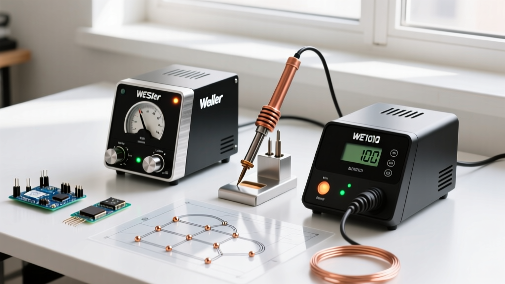
In professional electronics manufacturing and advanced DIY workbenches, the term soldering iron rod technically refers to the internal ceramic heating element and sensor assembly that drives the thermal transfer to the tip. Unlike older nichrome-wound barrels, modern ceramic rods offer rapid heat recovery and precise closed-loop temperature control. However, factory calibration can drift over time due to thermal cycling, oxidation at the sensor contacts, or physical degradation of the thermistor. Calibrating your station to the specific thermal output of its rod is essential for compliance with modern electronics assembly standards.
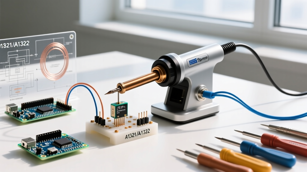
Before attempting any software or potentiometer offsets, you must understand the architecture of your specific heating rod. The two most common ceramic rod architectures in the industry are the Hakko A1321 and A1322 series. While they look nearly identical externally, their internal sensor technologies are fundamentally different, and confusing them during a replacement or calibration routine will result in catastrophic control loop failures.
| Rod Model | Heater Type | Sensor Element | Room Temp Resistance (25°C) | Pin Configuration | Typical 2026 Replacement Cost |
|---|---|---|---|---|---|
| Hakko A1321 | Ceramic | Thermistor (PTC) | ~43 Ω (Sensor Pins) | 5-Pin | $24.50 |
| Hakko A1322 | Ceramic | Thermocouple | ~2.5 Ω (Heater Pins) | 4-Pin | $28.00 |
| Weller RT Series | Ceramic | Thermocouple | Integrated / Proprietary | 4-Pin Locking | $42.00 |
Tools Required for Precision Calibration
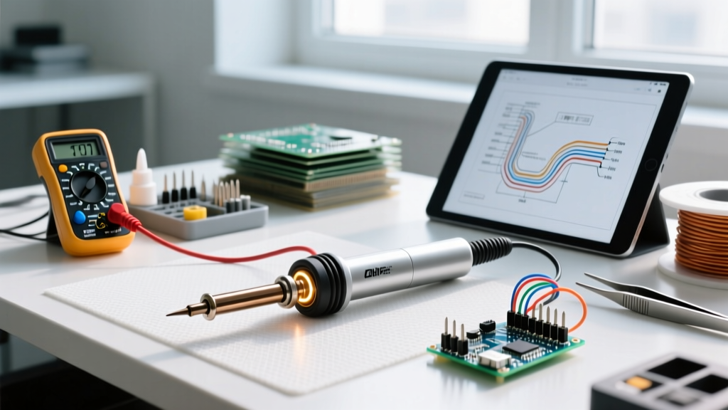
Do not attempt to calibrate a soldering iron rod by 'feel' or by observing the melt state of rosin-core solder. The human eye cannot accurately differentiate between 340°C and 380°C, a delta that can easily delaminate a 4-layer PCB or damage sensitive SMD components. You will need the following diagnostic and calibration tools:
- Digital Multimeter (DMM): A true-RMS meter with at least 0.1 Ω resolution on the low-ohms range. The Fluke 87V is the industry benchmark, though any high-quality bench meter will suffice for resistance checks.
- Tip Thermometer: A dedicated K-type thermocouple soldering tip thermometer (e.g., Hakko 191 or a calibrated generic equivalent). These feature a specialized surface-contact probe designed to read the convex curve of a chisel or conical tip. Budget around $35 to $150 depending on NIST-traceable certification requirements.
- High-Temp Thermal Coupling Compound: Optional but recommended for older stations where the tip-to-rod interface has degraded.
- Precision Screwdrivers: For accessing internal PCB trim-pots on analog stations (e.g., Weller WES51).
Phase 1: Cold-State Multimeter Diagnostics
Before applying power to the station, you must verify the physical integrity of the soldering iron rod's internal windings and sensor. Thermal drift is often a symptom of a failing rod rather than a software offset issue. Disconnect the handpiece from the station and set your multimeter to measure resistance (Ohms).
Testing the 5-Pin A1321 Rod
- Heater Element Check: Place your probes on Pins 1 and 2. You should read between 2.5 Ω and 3.5 Ω. A reading of 'OL' (Open Loop) indicates a fractured ceramic heating trace, requiring immediate rod replacement.
- Thermistor Sensor Check: Place your probes on Pins 3 and 4. At a standard room temperature of 25°C (77°F), the resistance should be approximately 43 Ω. If this reads significantly higher or fluctuates when you gently tap the handpiece, the internal sensor bonding wire is failing.
- Ground/Shield Check: Pin 5 should show continuity to the metal shaft of the handpiece and the tip retaining nut, ensuring ESD safety.
Testing the 4-Pin A1322 Rod
The A1322 uses a thermocouple, which does not exhibit high resistance like a thermistor. Pins 1 and 2 are the heater (approx. 2.5 Ω). Pins 3 and 4 are the thermocouple sensor. Because a thermocouple generates a millivolt signal based on temperature differentials rather than changing resistance, you must set your DMM to the millivolt (mV) range. Heating the tip slightly with a heat gun should yield a rising positive mV reading on Pins 3 and 4. If it reads 0 mV under heat, the thermocouple junction inside the rod is severed.
Phase 2: Active Thermal Offset Calibration
Once the rod passes the cold-state diagnostic, proceed to active thermal calibration. This process aligns the station's microcontroller reading with the actual temperature at the tip's working surface. We will use the ubiquitous Hakko FX-888D as the procedural baseline, though the physics apply universally.
- Preparation: Install a clean, well-tinned chisel tip (e.g., Hakko T18-D24). Ensure the tip is fully seated against the ceramic soldering iron rod. Any gap here introduces thermal lag that will ruin the calibration math.
- Enter Calibration Mode: Turn the station off. Press and hold the UP arrow button, then turn the power switch on. The display will show a blinking temperature, indicating offset mode.
- Set Target Baseline: Use the UP/DOWN arrows to set the display to 350°C (662°F). Press and hold the UP arrow for 2 seconds to lock it in. The station will now drive the rod to what it calculates as 350°C.
- Measure Actual Tip Temperature: Wait 3 minutes for thermal equilibrium. Apply a tiny bead of fresh solder to the tip to act as a thermal bridge. Press the K-type thermocouple probe of your tip thermometer firmly against the tinned surface. Record the exact reading (e.g., 338°C).
- Input the Offset: Press the UP arrow on the station to enter the actual measured temperature. Input '338' using the arrow keys. The station's firmware will now calculate the delta and apply a permanent offset to the rod's thermistor lookup table.
- Verify: Exit calibration mode, set the station to 300°C, and re-measure. The variance should now be within ±3°C.
Edge Cases: Thermal Coupling and Sensor Drift
If your station constantly overshoots or undershoots the target temperature despite a fresh calibration, the issue is rarely the rod's internal electronics. It is almost always a thermal coupling failure between the rod and the tip.
The Oxidation Barrier
Over months of use, the copper-alloy interior of the soldering tip develops a layer of cupric oxide where it slides over the ceramic rod. This oxide layer acts as a thermal insulator. The station's sensor (located inside the rod) reads that the tip is cold, so it pumps more current into the heater. By the time the heat penetrates the oxide layer, the tip is massively overheated, triggering the sensor to shut off. This results in wild temperature oscillations.
The Fix: Remove the tip and inspect the inner bore. If it is black or pitted, clean it gently with a brass wire brush or replace the tip entirely. Never use sandpaper, as it will alter the precise machining tolerances required for a friction-fit seal against the rod.
Compliance and Thermal Shock
Running a station uncalibrated or forcing high-heat offsets to compensate for a poor tip fit violates core manufacturing standards. As outlined in the IPC J-STD-001 requirements for soldered electrical assemblies, thermal profiles must be strictly controlled to prevent hidden defects like pad lifting or internal micro-cracking in MLCCs (Multi-Layer Ceramic Capacitors). A poorly coupled rod forces the operator to dwell longer on the joint, exponentially increasing the risk of thermal damage to the PCB substrate.
"Thermal shock to components and PCB laminates is primarily caused by excessive dwell times resulting from poor thermal transfer at the iron-to-tip interface, not necessarily the absolute temperature setting of the station." — Benchmarking Thermal Profiles in Lead-Free Assembly
Frequently Asked Questions
Can I use an A1322 rod in a station designed for an A1321?
No. The A1321 relies on a thermistor (resistance-based), while the A1322 uses a thermocouple (voltage-based). If you plug an A1322 rod into an A1321 circuit, the station's op-amp will read the near-zero resistance of the thermocouple as a 'short circuit' or an infinitely high temperature, immediately throwing an H1 error code and shutting down the heater to prevent a fire hazard.
How often should I recalibrate my soldering iron rod?
For hobbyists, an annual calibration check is sufficient. For professional environments operating under ISO 9001 or IPC-A-610 compliance, calibration must be verified every 3 to 6 months, or immediately after the heating rod or handpiece cord is replaced. Always log the offset values in your maintenance tracker.
Why does my station display 'H1' or 'S-E' after a new rod installation?
These error codes indicate an open or shorted sensor circuit. 90% of the time, this is caused by a bent pin inside the handpiece's ceramic connector plug. Use a magnifying loupe to inspect the 4 or 5 brass pins. If one is pushed back into the plastic housing, it will not make contact with the station's receptacle, resulting in a sensor failure code. Carefully extract it with needle-nose pliers and reseat it.