
The Physics of the Pistol Soldering Iron
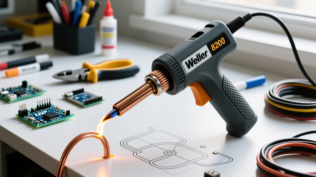
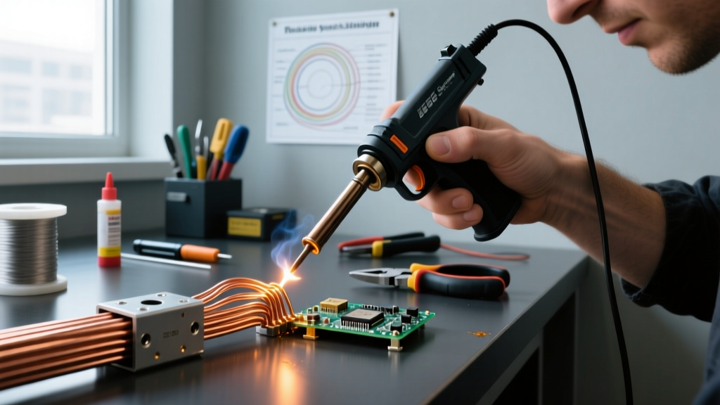
Unlike standard ceramic or mica-heater pen irons that rely on thermal conduction from an internal element to the tip, a pistol soldering iron—universally known in the trade as a soldering gun—operates on the principles of a step-down transformer. When you squeeze the trigger, mains voltage (120V or 230V) is applied to a primary coil wrapped around an iron core. The secondary coil consists of a single turn of thick copper or aluminum, which forms the physical tip of the tool.
Because the secondary winding has only one turn, the voltage drops to a fraction of a volt (typically 0.15V to 0.35V), while the current spikes to hundreds of amps. In a standard 240W model like the legendary Weller D550PK, the tip can see upwards of 800 amps of current. The resistive heating (I²R) of the copper loop itself generates the heat, allowing the tip to reach soldering temperatures in under three seconds. This instant-heat, high-thermal-mass delivery system makes the pistol soldering irreplaceable for specific heavy-duty electrical tasks, provided the operator understands its unique physical limitations.
When to Deploy a Soldering Gun (and When to Avoid It)
The pistol soldering iron is a brute-force instrument designed for high-thermal-mass joints. It is the gold standard for tasks where a 60W or 80W pen-style iron would simply act as a heat sink, resulting in cold, crystalline joints.
Ideal Applications
- Heavy-Gauge Wiring: Soldering 10 AWG down to 4/0 AWG battery cables, solar busbars, and automotive chassis grounds.
- Thick Copper Fabrication: Stained glass copper foil work, copper roofing seams, and thick sheet metal grounding straps.
- Large Mechanical Lugs: Attaching ring terminals and spade connectors to thick stranded wire where mechanical crimping is supplemented by solder for environmental sealing.
The EMF Hazard: Where NOT to Use It
The most critical, yet least understood, characteristic of the pistol soldering iron is the intense alternating magnetic field (EMF) generated by the high-current tip loop. According to guidelines referenced in IPC J-STD-001 for electronic assemblies, localized magnetic fields can induce destructive voltage spikes in nearby conductive paths.
Never use a soldering gun on or near:
- Printed Circuit Boards (PCBs) with sensitive semiconductors (MOSFETs, op-amps).
- Components containing magnetic cores (inductors, transformers, Hall-effect sensors).
- Unpowered EEPROM or flash memory chips, as the induced EMF can corrupt data or blow gate oxides.
For PCB work, always use a temperature-controlled pen station. Reserve the pistol grip strictly for heavy, isolated wiring and chassis work.
Heavy-Gauge Wiring Technique: Step-by-Step
Soldering a 4 AWG battery cable requires a fundamentally different approach than soldering a 22 AWG breadboard jumper. The goal is to bring the entire mechanical joint above the solder's liquidus temperature simultaneously without melting the wire insulation. The following methodology aligns with NASA Workmanship Standards for high-reliability wire terminations.
1. Mechanical Preparation and Stripping
Solder should never be relied upon for mechanical strength. Before applying heat, the joint must be mechanically secure. For solid wire, use a Western Union splice. For heavy stranded wire (10 AWG to 4/0 AWG), strip exactly 0.75 to 1.5 inches of insulation depending on the lug depth. Twist the strands tightly and insert them into the barrel of the lug, or create a tight J-hook if splicing wire-to-wire. Use a wire brush or fiberglass scratch pen to remove any surface oxidation from the copper strands and the inside of the lug barrel.
2. Flux Application and Thermal Staging
Heavy-gauge copper acts as a massive heat sink. Liquid fluxes will boil off and burn before the core of the wire reaches temperature. You must use a high-viscosity, tacky rosin flux (such as MG Chemicals 8341 or Chip Quik SMD291AX). Inject the tacky flux deep into the stranded wire and coat the outside of the lug. The flux will act as a temporary thermal interface material, bridging the microscopic air gaps between the copper strands and accelerating heat transfer.
3. The Two-Stage Trigger Method
Most professional pistol soldering irons, including the Weller D550 and 9400 series, feature a dual-stage trigger. The first pull engages a lower wattage (e.g., 120W), and a full squeeze engages the high wattage (e.g., 240W).
- Initial Heat (Full Squeeze): Press the copper loop directly against the thickest part of the joint (usually the bottom of the lug barrel). Squeeze the trigger fully to the 240W stage. Hold for 3 to 5 seconds. You will see the flux bubble vigorously and turn amber.
- Maintenance Heat (Half Squeeze): Release the trigger slightly to the 120W detent. This prevents the copper loop from overheating and oxidizing while maintaining the joint's thermal saturation.
- Feed the Solder: Apply 0.062-inch to 0.125-inch diameter 63/37 eutectic solder to the opposite side of the joint from where the iron is touching. When the flux flows and the solder wicks instantly into the wire strands via capillary action, the joint is at temperature.
- Cool Down: Release the trigger completely and hold the wire still until the solder transitions from shiny liquid to a dull, solid frost. Do not blow on the joint, as this can cause micro-fractures in the crystalline structure.
Thermal Mass Matching Matrix
Matching your tip thickness, solder diameter, and gun wattage to the wire gauge is critical for preventing cold joints and insulation damage. Use this reference matrix for standard copper wiring:
| Wire Gauge (AWG) | Tip Loop Thickness | Gun Wattage Setting | Solder Diameter | Max Heat Time |
|---|---|---|---|---|
| 18 - 14 AWG | Standard (1/16") | 100W - 120W (Low) | 0.031" - 0.040" | 2 - 3 Seconds |
| 12 - 10 AWG | Standard (1/16") | 200W - 240W (High) | 0.050" - 0.062" | 3 - 5 Seconds |
| 8 - 4 AWG | Heavy Duty (1/8") | 240W+ (High) | 0.080" - 0.125" | 5 - 8 Seconds |
| 2 - 4/0 AWG | Custom / Twin-Tip | 300W+ (Pro Gun) | 0.125"+ | 8 - 15 Seconds |
Solder Alloy Selection for High-Mass Joints
When using a pistol soldering iron, alloy selection dictates your success rate. While the industry has largely moved to lead-free alloys like SAC305 (Tin/Silver/Copper) for PCB manufacturing, 63/37 Tin/Lead (Eutectic) remains the undisputed king of heavy-gauge field wiring and chassis soldering.
The 63/37 alloy is eutectic, meaning it transitions from solid to liquid at a single, sharp temperature point (183°C / 361°F). It has no 'plastic' or 'pasty' phase. In contrast, standard 60/40 solder has a plastic range of about 7°C. When soldering massive 4 AWG battery cables that take 10 seconds to cool, a 60/40 joint is highly susceptible to disturbance during that plastic phase, resulting in a disturbed, high-resistance joint. Furthermore, 63/37 exhibits superior wetting characteristics on heavy, slightly oxidized copper surfaces, requiring less aggressive fluxes and reducing the risk of long-term corrosion under heat shrink tubing.
Common Failure Modes and Edge Cases
Tin Leaching and Tip Destruction
The secondary loop of a soldering gun is typically bare copper. If you attempt to use a standard copper loop with lead-free SAC305 solder, the high tin content and elevated temperatures (217°C+) will cause 'tin leaching.' The tin aggressively dissolves the copper tip, often destroying the loop in a matter of hours. If your project strictly mandates lead-free compliance (such as certain automotive or aerospace contracts), you must source specialized iron-plated tips designed for soldering guns, or switch to a high-wattage ceramic pen station like the Hakko FX-601.
Insulation Heat Creep
Copper is an exceptional thermal conductor. If you apply a 240W soldering gun to a 10 AWG wire for more than 6 seconds, the heat will travel laterally down the wire strands via conduction, melting the PVC or XLPE insulation inches away from the joint. To combat this, use a 'heat dam.' Clamping a pair of heavy steel locking pliers or an alligator clip to the bare wire between the joint and the insulation will absorb the lateral heat sink, protecting the wire jacket.
Tip Arcing and Hardware Torquing
A frequent point of failure with pistol soldering irons is the physical connection between the copper tip and the gun's secondary bus bars. The tip is held in place by brass slotted nuts. Because the tool undergoes rapid thermal expansion and contraction, these nuts loosen over time. If the connection is loose, the massive secondary current will arc across the threads. This causes severe pitting, increases electrical resistance, and eventually welds the brass nut to the bus bar, making tip changes impossible. Expert Maintenance Tip: Every 20 hours of use, allow the gun to cool completely and retorque the tip mounting nuts using a hollow-shaft nut driver. Apply a microscopic dab of high-temperature anti-seize compound to the threads to prevent galvanic corrosion between the copper tip and brass nut.
Summary
The pistol soldering iron is a specialized, high-energy tool that bridges the gap between standard electronics work and heavy industrial joining. By respecting its electromagnetic footprint, utilizing eutectic alloys, and mastering the two-stage trigger technique, you can produce aerospace-grade, high-reliability terminations on the heaviest gauge wiring encountered in automotive, marine, and renewable energy systems.