
The Critical Role of Pencil Soldering Iron and Station Calibration
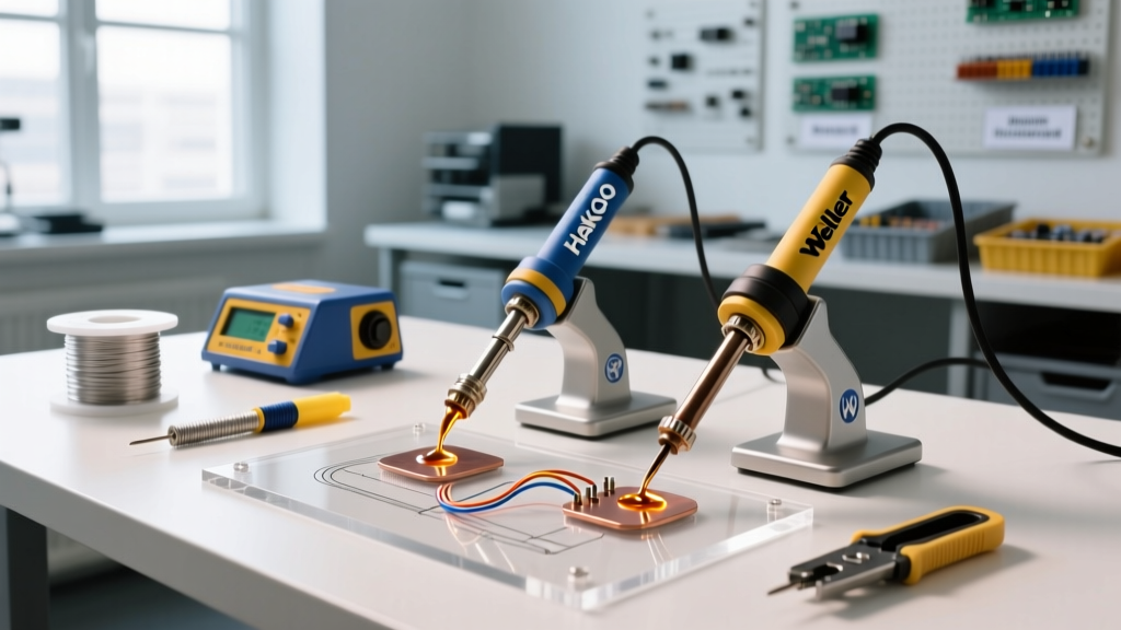
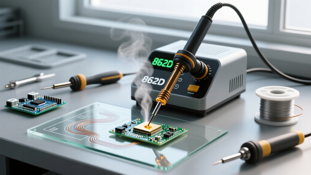
When configuring a new electronics workbench or maintaining an existing production line, executing a proper pencil soldering iron and station calibration is non-negotiable. Even premium closed-loop systems like the Hakko FX-888D Digital Soldering Station or the Weller WE1010NA rely on internal thermocouples that degrade over time. If the digital display reads 350°C but the actual tip temperature is 320°C, you risk cold solder joints, incomplete wetting, and failed IPC Class 3 inspections. Conversely, an uncalibrated station running 20°C too hot will rapidly oxidize your tips and delaminate PCB pads.
This comprehensive setup and calibration tutorial bridges the gap between factory defaults and real-world thermal accuracy. We will cover the exact procedures for measuring tip temperature delta, applying firmware offsets, and troubleshooting the most common thermal failure modes encountered in modern DIY and professional labs.
According to the IPC J-STD-001 standard for soldered electrical assemblies, maintaining strict temperature control at the soldering interface is critical for proper intermetallic compound (IMC) formation and preventing thermal damage to sensitive components.
Essential Equipment for Accurate Calibration
Before initiating the pencil soldering iron and station calibration sequence, you must gather specialized thermal measurement tools. Standard multimeter thermocouples are insufficient because they lack the thermal mass and geometry required to interface with a soldering tip.
- Digital Soldering Thermometer: A dedicated unit like the Hakko 191 or Weller WSDH1 (Retail: $130 - $180). These devices feature fast-sampling ADCs designed specifically for the rapid heat transfer of soldering tips.
- K-Type Curved Thermocouple Probe: You need a probe with a curved wire tip (often designated as a 'T' or 'S' style probe) to match the convex profile of standard chisel and bevel tips like the Hakko T18-B or Weller ETA.
- Thermal Transfer Compound: A small dab of high-temperature thermal paste ensures accurate heat transfer between the tip and the thermocouple bead, eliminating air gaps that cause false low readings.
- Tip Tinner and Brass Wool: For preparing the working face of the iron prior to measurement.
Step-by-Step Pencil Soldering Iron and Station Calibration Protocol
Follow this exact sequence to ensure your closed-loop PID controller is accurately mapped to the physical temperature of your pencil soldering iron.
Phase 1: Tip Preparation and Thermal Equilibrium
- Inspect and Clean: Remove the pencil soldering iron from the station. Ensure the tip is fully seated against the ceramic heating element. Any gap here will cause massive thermal lag. Clean the tip using damp cellulose sponge and brass wool.
- Apply Fresh Solder: Tin the working face of the tip with fresh, flux-cored 63/37 or SAC305 solder. An oxidized tip will act as a thermal insulator, rendering your calibration readings useless.
- Set Baseline Temperature: Power on the station and set the target temperature to 350°C (662°F), the industry standard baseline for lead-free SAC305 alloys.
- Wait for Equilibrium: Allow the station to heat up and cycle for a minimum of 5 minutes. The PID controller needs time to stabilize the thermal mass of the entire pencil assembly, not just the outer shell.
Phase 2: Measuring the Temperature Delta
- Apply Thermal Compound: Place a microscopic amount of thermal transfer compound on the curved wire of your K-type thermocouple probe.
- Position the Probe: Press the curved probe wire directly against the tinned working face of the pencil soldering iron tip. Hold it at a 45-degree angle, applying gentle, consistent pressure. Do not press so hard that you bend the probe wire.
- Record the Peak Reading: Watch the digital thermometer. The temperature will spike, dip slightly as the station's sensor detects the heat sink effect of the probe, and then recover. Record the stabilized peak temperature. For example, if the station displays 350°C but the thermometer stabilizes at 338°C, your delta is -12°C.
Phase 3: Applying the Firmware Offset
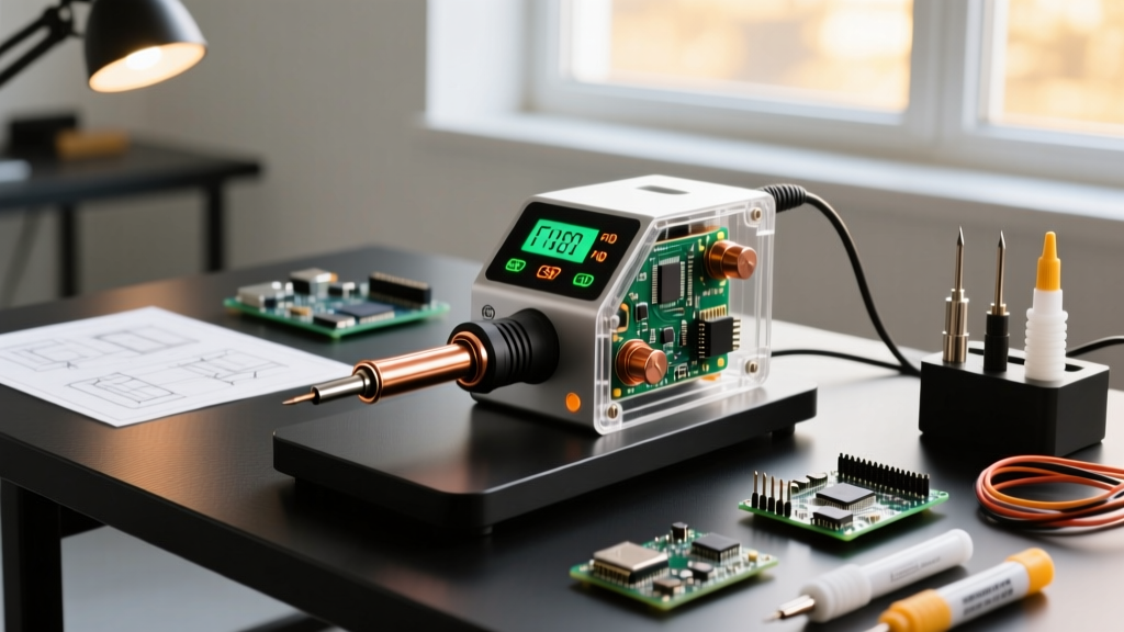
Once you have your delta, you must input this offset into the station's microcontroller. Using the highly popular Hakko FX-888D as our reference model, the process is as follows:
- Turn the power switch to the OFF position.
- Press and hold the UP arrow button on the front panel.
- While holding the UP button, turn the power switch ON. The display will show '000' or prompt for a password (default is usually '000' or '138' depending on the firmware revision).
- Use the UP and DOWN arrows to input the password and press ENTER.
- The display will now show the current offset value. Use the arrows to adjust this value to match your measured delta (e.g., add +12°C to compensate for the 338°C reading).
- Press and hold the ENTER button for 3 seconds to save the new calibration profile, then power cycle the station.
Calibration Frequency and Maintenance Matrix
The frequency of your pencil soldering iron and station calibration depends heavily on your usage volume and environmental conditions. Use the matrix below to schedule your maintenance.
| Usage Profile | Environment | Calibration Interval | Expected Drift |
|---|---|---|---|
| Heavy Production (8+ hrs/day) | Controlled Lab | Every 30 Days | ±8°C to ±12°C |
| Prototyping / R&D (2-4 hrs/day) | Standard Office | Every 90 Days | ±4°C to ±7°C |
| DIY / Hobbyist (1-2 hrs/week) | Home Garage | Every 6 Months | ±2°C to ±5°C |
| Post-Tip Replacement | Any | Immediate | Varies by tip batch |
Troubleshooting Common Calibration Edge Cases
Even with perfect technique, you may encounter anomalies during the pencil soldering iron and station calibration process. Here is how to diagnose and resolve the most frequent edge cases.
Symptom: Thermometer Reading Fluctuates Wildly (±15°C)
Root Cause: Poor thermal coupling or a degraded thermocouple wire inside the probe. If the ambient room temperature is below 18°C or there is an active HVAC draft hitting the workbench, the micro-environment around the tip will destabilize.
Solution: Shield the tip and probe from drafts using a silicone soldering mat or a small cardboard windbreak. Ensure your thermal compound has not dried out. If fluctuations persist, replace the K-type probe wire; they are considered consumable items and typically last 500-800 measurements.
Symptom: Station Maxes Out but Tip Reads Extremely Low
Root Cause: If your station display reads 480°C (its maximum limit) but the external thermometer reads only 220°C, the closed-loop feedback is broken. The station is pumping maximum voltage into the heater because it cannot detect the tip's actual temperature. This is almost always caused by a severed thermocouple sensor wire inside the pencil handle or a cracked ceramic heating element.
Solution: Disassemble the pencil handle and inspect the 4-pin or 5-pin connector. Look for carbon tracking or melted insulation. In 90% of these cases, replacing the heating element (Part # B2032 for Hakko, approx. $18) resolves the issue immediately.
Symptom: Consistent Negative Drift Across Multiple Tips
Root Cause: Internal oxidation of the station's heating element core. Over years of use, the outer metal sheath of the ceramic heater oxidizes, creating a thermal barrier between the heater and the inner wall of the soldering tip.
Solution: Remove the tip and the heating element. Gently polish the exterior of the ceramic heater with a fiberglass scratch pen or ultra-fine emery cloth to remove the oxidation layer. Re-tin the inside of the tip before reassembly to ensure optimal thermal conductivity.
Final Thoughts on Thermal Accuracy
Treating your pencil soldering iron and station calibration as a one-time factory setup is a critical mistake that leads to degraded joint quality and wasted consumables. By integrating this 10-minute calibration protocol into your regular maintenance schedule, you ensure that your PID controller operates with the precision required for modern, fine-pitch SMD components and high-reliability through-hole assemblies. Always trust the external digital thermometer over the station's front-panel display, and adjust your offsets accordingly to maintain strict adherence to industry workmanship standards.