
The Thermodynamics of DIY Soldering
Building a homemade soldering iron is a rite of passage for hardcore electronics hobbyists and survivalists alike. However, the internet is saturated with dangerous, fundamentally flawed tutorials suggesting you wrap nichrome wire around a nail or heat a copper wire with a butane torch. As an electrical engineer, I can definitively state that these methods fail the basic laws of thermodynamics required for reliable PCB assembly. A viable DIY soldering tool must balance thermal mass, active heat recovery, and precise temperature control to meet modern electronics standards.
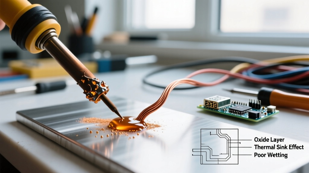
When a soldering tip contacts a copper ground plane on a printed circuit board, heat is rapidly wicked away. If the tool lacks sufficient thermal recovery, the solder joint cools below the liquidus point before proper metallurgical wetting occurs, resulting in a cold, high-resistance joint. According to the IPC soldering standards, reliable through-hole and surface-mount joints require precise thermal profiles to ensure proper intermetallic compound (IMC) formation. A poorly designed homemade iron will consistently fail these criteria.
Why the 'Nail and Torch' Method Fails
Bare nichrome wire wrapped around a steel nail suffers from three fatal flaws:
- Rapid Oxidation: Nichrome oxidizes heavily at temperatures exceeding 350°C, creating an insulating layer that prevents heat transfer to the workpiece.
- Zero Thermal Mass: A steel nail cannot store enough joules of thermal energy to bridge the heat-sink effect of a multi-layer PCB.
- Galvanic and Electrical Hazards: Mains-powered DIY wire wraps lack isolation, posing a severe electrocution risk and introducing 50/60Hz AC noise directly into sensitive microcontrollers.
The 12V Cartridge Heater Build (Expert Approach)
The only expert-approved method for building a high-performance homemade soldering iron in 2026 utilizes a 12V DC cartridge heater—specifically the 6mm x 30mm 60W units commonly used in 3D printer hotends (like the E3D V6 compatible heaters). This approach provides high watt density, safe low-voltage DC operation, and a form factor that can be adapted to accept standard Hakko T12 or TS100 style tips with minimal machining.
Bill of Materials & Sourcing
To build a thermally stable DIY station, you will need the following components. Total cost is approximately $35 to $45 USD.
- Heating Element: 12V 60W Cartridge Heater (6mm diameter, 30mm length). Resistance should measure exactly 2.4 ohms.
- Thermal Sensor: K-Type Thermocouple (bare wire, fiberglass insulated) paired with a MAX6675 cold-junction compensation module.
- Controller: A digital PID temperature controller (e.g., Inkbird ITC-100VH or a custom Arduino Nano PID loop utilizing the PID_v1 library).
- Tip Assembly: C110 Oxygen-Free Copper rod (machined to accept the heater and thermocouple) or a modified brass sleeve. C110 copper offers a thermal conductivity of 401 W/m·K, vastly outperforming 6061 aluminum (167 W/m·K).
- Power Supply: 12V 10A Switching Power Supply (120W capacity to handle inrush current and prevent voltage sag).
Step-by-Step Assembly
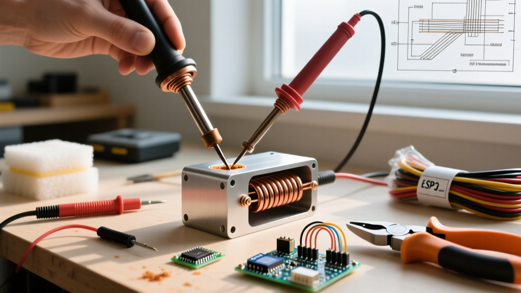
- Machine the Thermal Core: Drill a 6.1mm blind hole into the C110 copper rod to accept the cartridge heater. Ensure a tight friction fit; any air gap will act as a thermal insulator, causing the heater to overheat internally while the tip remains cold.
- Sensor Placement: Drill a secondary 2mm hole intersecting the tip's working end. Insert the K-type thermocouple here. Placing the sensor at the tip (rather than the base) drastically reduces the PID control loop lag time.
- Wire the PID: Connect the MAX6675 to your microcontroller or the input terminals of the Inkbird. Wire the solid-state relay (SSR) in series with the cartridge heater's positive lead.
- Tune the PID: A thermal system with high mass requires careful tuning. Start with a high Proportional (P) gain, minimal Integral (I) to prevent windup, and a moderate Derivative (D) to anticipate temperature overshoot. Expect 4 to 6 oscillation cycles before the system stabilizes at your 350°C setpoint.
Power Supply Matching & Thermal Recovery
The power source dictates your iron's ability to recover heat between solder joints. Below is a comparison of common 12V power sources used in DIY builds.
| Power Source | Nominal Voltage | Peak Wattage (at 2.4Ω) | Voltage Sag Under Load | Thermal Recovery Time (to 350°C) |
|---|---|---|---|---|
| 3S LiPo Battery (5000mAh) | 11.1V | 51W | High (drops to 10.5V) | 14-18 seconds |
| 12V 10A Switching PSU | 12.0V | 60W | Negligible | 8-11 seconds |
| 12V Lead-Acid (SLA) | 12.6V | 66W | Moderate | 6-9 seconds |
| 14.4V Tool Battery (Adapter) | 14.4V | 86W (Overdriven) | Low | 3-5 seconds |
Expert Warning: Overdriving a 12V cartridge heater with a 14.4V or 16.8V (4S LiPo) source pushes the wattage past 85W. While this yields incredible thermal recovery, it will rapidly degrade the internal magnesium oxide insulation of cheap cartridge heaters, leading to catastrophic short-circuits.
Critical Safety Protocols & Failure Modes
When constructing a homemade soldering iron, safety cannot be an afterthought. You are dealing with temperatures that exceed the auto-ignition point of many common workbench materials.
Thermal Runaway and SSR Failure
The most common failure mode in DIY thermal systems is a shorted Solid State Relay (SSR). If the SSR fails closed, the PID controller loses the ability to cut power, and the cartridge heater will continuously draw 60W. Without a thermal fuse, the copper tip will exceed 600°C, melting the PTFE insulation on your wiring and potentially igniting the workbench. Always install a physical, non-resettable thermal fuse (rated for 400°C) in series with the heater element.
Lead and Flux Fume Mitigation
Even if you use lead-free SAC305 solder, the rosin-based fluxes used in electronics assembly release colophony fumes when heated, which are known respiratory sensitizers. Furthermore, if you are repairing older equipment with Sn63/Pb37 solder, lead exposure is a severe risk. Always follow the CDC NIOSH guidelines on lead safety, which mandate local exhaust ventilation (LEV) and strict hand-washing protocols. Never eat or drink at a bench where a homemade iron is actively being used.
Industry Standard Note: Aerospace and medical electronics require strict adherence to thermal profiles to prevent component damage. The NASA Electronic Parts and Packaging (NEPP) program explicitly outlines the dangers of uncalibrated, uncontrolled soldering tools, noting that excessive tip temperatures can cause pad delamination and internal die cracking in ICs. If your DIY iron lacks a calibrated PID loop, restrict its use to non-critical, hobbyist wire splicing.
Cost-Benefit Analysis: DIY vs. Commercial Smart Irons (2026)
Is building a homemade soldering iron economically viable in 2026? Let us look at the current market. A high-quality commercial smart iron like the Pine64 Pinecil V2 retails for approximately $28, while the Miniware TS101 sits around $55. These commercial units feature RISC-V processors, rapid PD (Power Delivery) negotiation, and integrated accelerometers for sleep modes.
By contrast, a robust DIY build utilizing an Inkbird PID, a benchtop power supply, and machined copper will cost upwards of $65 and take a weekend to assemble. Therefore, you should not build a homemade soldering iron to save money. You should build it to understand the Seebeck effect in thermocouples, to master PID tuning algorithms, and to create a bespoke, high-thermal-mass tool for specialized applications (like soldering heavy 10 AWG silicone wires or large copper pour ground planes) where standard smart irons might struggle without a dedicated DC power brick.
Frequently Asked Questions
Can I just use a high-wattage resistor as a heating element?
No. Power resistors (like the 50W aluminum-housed chassis mount resistors) are designed to dissipate heat into the ambient air, not to transfer it conductively into a small surface area. Their thermal resistance to a soldering tip would be disastrous.
How do I tin a raw copper tip on my DIY iron?
Raw C110 copper oxidizes instantly at 350°C, preventing solder wetting. Before your first heat-up, coat the working end of the copper tip with a generous layer of phosphoric acid-based flux and submerge it in molten solder, or aggressively abrade it with fine sandpaper while applying rosin flux and solder simultaneously as it reaches 250°C. For long-term use, consider electroplating the tip with a thin layer of iron, followed by chrome, mimicking commercial tip manufacturing processes.
What wire gauge should I use for the 12V DC connection?
At 60W and 12V, the system draws 5 amps continuously. According to standard AWG current capacity charts, you must use a minimum of 16 AWG silicone wire for the main power trunk, and no less than 18 AWG for the final flexible segment leading to the iron handle to prevent voltage drop and hazardous wire heating.