
The Anatomy of a Soldering Iron Set: Beyond the Iron
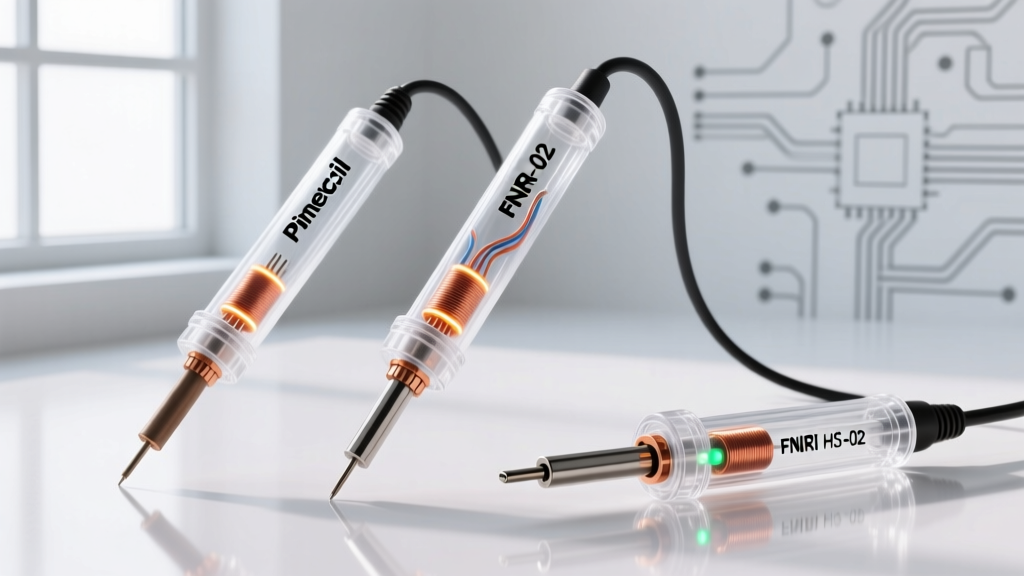
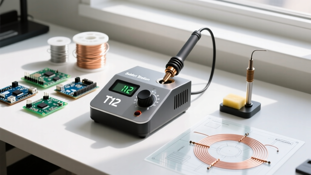
When hobbyists and professionals purchase a soldering iron set, they are typically acquiring a complete thermal ecosystem. Whether you are using a high-end digital station like the Hakko FX-888D, a smart iron like the Pine64 Pinecil V2, or a generic 60W adjustable kit with interchangeable tips, the longevity of your equipment depends entirely on systematic maintenance. A soldering iron set is only as reliable as its weakest component—usually the tip plating, the ceramic heating element, or the mechanical seals of the desoldering pump. In 2026, with lead-free SAC305 alloys demanding higher thermal profiles and aggressive flux chemistries, proactive troubleshooting is no longer optional. This guide provides deep-level diagnostic protocols, exact multimeter readings, and maintenance schedules to keep your soldering iron set performing to IPC standards.
Diagnostic Matrix: Troubleshooting Common Set Failures
Before disassembling your station or discarding a seemingly dead iron, run through this diagnostic matrix. Most field failures in a soldering iron set are related to oxidation, mechanical fatigue, or sensor decoupling.
| Symptom | Probable Root Cause | Targeted Fix |
|---|---|---|
| Tip turns black; solder balls up and rolls off | Severe oxidation due to dry-heating or excessive temperature (>400°C) | Cool to 150°C, apply tip tinner (e.g., Hakko 599B), re-tin with 63/37 rosin-core solder. |
| Digital display blinks or flashes error code | Thermocouple sensor failure or broken heater wire | Test heater continuity with a multimeter; replace heating element if open circuit. |
| Iron heats up but melts solder very slowly | Thermal decoupling; flux carbon buildup between heater and tip | Remove tip, clean heater shaft with brass wool and isopropyl alcohol (IPA). |
| Desoldering pump loses suction after 2-3 uses | Degraded Viton O-ring or clogged PTFE nozzle liner | Disassemble pump, replace O-ring, and clear solder slag from the PTFE tube. |
| Adjustable dial (generic sets) feels loose/no response | Internal potentiometer wiper worn or triac failure | Replace the potentiometer (usually 500kΩ) or upgrade to a PID-controlled smart iron. |
Thermal Recovery and Heating Element Diagnostics
The core of any soldering iron set is the heating element. In modern stations, the sensor and heater are often integrated to provide rapid thermal recovery. When a station fails to heat, you must isolate the failure to the station's PCB, the wiring harness, or the handpiece element.
Step-by-Step Multimeter Testing
- Disconnect Power: Never test continuity on a live circuit. Unplug the station and detach the handpiece.
- Identify Pins: For a standard Hakko FX-888D (using a T18 series tip and ceramic heater), the handpiece connector has 5 pins. Pins 1 and 2 are the heating element; Pins 3 and 4 are the thermocouple sensor.
- Test the Heater: Set your multimeter to Ohms (Ω). Place probes on Pins 1 and 2. A healthy 24V ceramic heater should read between 2.0Ω and 4.0Ω. If it reads 'OL' (Open Loop), the internal wire is snapped, and the element must be replaced (approx. $35 USD).
- Test the Sensor: Move probes to Pins 3 and 4. A healthy thermocouple will read very low resistance, typically 1.0Ω to 2.0Ω at room temperature. An open reading here explains a blinking display and requires a full handpiece replacement.
Expert Note: For smart irons like the Pinecil V2 or TS100 that use DC barrel jacks or USB-C PD, a failure to heat is rarely the iron itself. Test the power delivery negotiation using a USB-C multimeter tester. If the iron requests 20V but the power bank only negotiates 12V, the iron will display a low-voltage warning and shut off the heater to protect the MOSFETs.
The NASA-Standard Tip Tinning Protocol
Maintaining the iron-plated copper tips included in your soldering iron set requires strict adherence to thermal management. According to the NASA Workmanship Standards for soldering, a tip must never be heated dry. The iron plating is microscopic (often just 0.003 to 0.005 inches thick); once flux burns through this layer, the underlying copper dissolves into the molten solder, creating pitting and permanent failure.
Daily Maintenance Routine
- Startup: Apply a generous bead of 63/37 (leaded) or SAC305 (lead-free) solder to the tip while it is heating up. This creates a sacrificial oxidation barrier before the tip reaches active working temperatures.
- During Use: Never use a wet cellulose sponge. The rapid thermal shock drops the tip temperature by up to 100°C instantly, stressing the ceramic heater and micro-cracking the iron plating. Use a dry brass wire sponge (like the Hakko 599B) to clean excess solder and flux carbon.
- Shutdown: Never turn off the station with a clean tip. Melt a large blob of solder over the entire working surface of the tip to seal it from ambient oxygen as it cools. This is known as 'tinning for storage'.
Accessory Upkeep: Desoldering Pumps and Tweezers
A comprehensive soldering iron set includes desoldering tools and precision tweezers. These mechanical accessories degrade rapidly if ignored.
Rebuilding the Desoldering Pump
The manual desoldering pump (often a generic clone or a brand-name Soldapullt) relies on a vacuum seal. Over time, the high temperatures of molten solder and the chemical exposure to rosin flux cause the internal O-ring to flatten and the PTFE (Teflon) nozzle to char.
- Unscrew the nozzle tip and extract the PTFE liner.
- Soak the liner in 99% Isopropyl Alcohol to dissolve rosin residue. If the PTFE is melted or restricted by solder slag, replace it (standard OD is usually 3mm).
- Remove the plunger rod and inspect the main Viton O-ring. If it shows a 'set' (a permanent flat edge), replace it. A standard 5mm ID x 1.5mm cross-section Viton O-ring costs less than $0.10 in bulk but restores 100% of the vacuum suction.
- Lubricate the new O-ring with a microscopic amount of silicone grease—never use petroleum jelly, which will degrade the rubber and contaminate your PCBs.
Repair vs. Replace: 2026 Cost Breakdown
Knowing when to repair a component of your soldering iron set versus replacing the entire unit is crucial for budget management. Below is a real-world cost analysis for popular 2026 setups.
| Equipment Tier | Common Failure Point | Repair Cost | Replacement Cost | Verdict |
|---|---|---|---|---|
| Generic 60W Adjustable Kit ($25) | Heating element / Mica wrap | $8 (Element) | $25 (Full Set) | Replace: Labor and safety risks outweigh savings. |
| Hakko FX-888D Station ($115) | Ceramic Heater (B2032) | $35 (Part) | $115 (Station) | Repair: Highly cost-effective; takes 5 minutes. |
| Weller WE1010NA ($130) | Iron Tip (RT Series) | N/A (Consumable) | $12 (Per Tip) | Replace Tip: Integrated sensor means the whole tip is tossed. |
| Pine64 Pinecil V2 ($26) | USB-C Port / MOSFET | $2 (Soldering) | $26 (New Iron) | Repair: Only if you have micro-soldering skills; otherwise replace. |
Safety, Fume Extraction, and Industry Standards
Maintenance of your soldering iron set also extends to safety compliance. The fluxes used in modern solder wires (especially no-clean and water-soluble variants) release volatile organic compounds (VOCs) and aldehydes when heated. The Occupational Safety and Health Administration (OSHA) strictly regulates airborne lead and particulate exposure in professional environments. Even for home DIYers, relying on a small carbon-filter fan built into a soldering iron set is insufficient. True maintenance requires replacing the activated carbon filters in your fume extractor every 40 to 50 hours of active soldering time, as the carbon becomes saturated and stops adsorbing harmful rosin vapors. Furthermore, adhering to IPC standards for rework ensures that your maintenance practices do not introduce electrostatic discharge (ESD) or thermal damage to sensitive components.
Frequently Asked Questions
Q: Can I use a file or sandpaper to clean a heavily oxidized tip in my soldering iron set?
A: Absolutely not. Modern soldering iron tips are made of a copper core plated with a microscopic layer of iron and chromium. Filing or sanding will strip this plating instantly, exposing the copper. The copper will then dissolve into the molten solder, ruining the tip in minutes. Always use chemical tip tinner or a brass wire sponge.
Q: My generic soldering iron set has a loose dial and the temperature fluctuates wildly. Is it fixable?
A: Generic irons use cheap triac-based phase-angle control circuits with low-tolerance potentiometers. The fluctuation is usually caused by carbon tracking inside the potentiometer. You can attempt to clean it with contact cleaner, but the permanent fix is to retire the iron and invest in a PID-controlled smart iron like the Pinecil V2 or FNIRSI HS-01, which use digital encoders rather than analog dials.
Q: How often should I replace the brass wool in my tip cleaner?
A: The brass wool itself rarely needs replacing unless it becomes physically matted with solder slag. However, you must empty and clean the metal catcher bowl beneath the brass wool monthly. If the bowl fills with solder dross and flux residue, it will conduct heat back up into the brass wool, reducing its thermal shock properties and potentially burning your fingers when cleaning the tip.