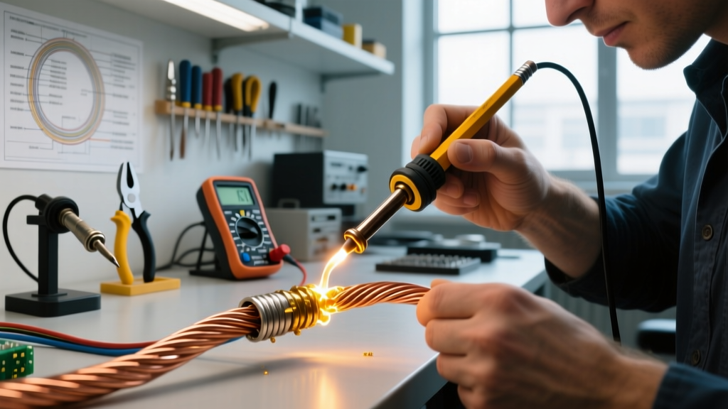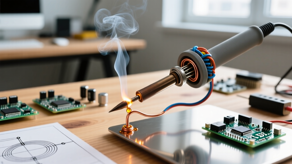

The Metallurgy of Heating: Why Nichrome 80 Dominates Soldering Elements
When a soldering station's heating element burns out, the culprit is almost always the degradation of the internal resistance wire. For DIY repair technicians, custom CNC tool builders, and electronics hobbyists, understanding how to select, wind, and calibrate nichrome wire for soldering iron applications is a critical skill. While Kanthal (FeCrAl) is popular for high-temperature kiln elements, Nichrome 80 (80% Nickel, 20% Chromium) remains the undisputed standard for soldering irons operating in the 200°C to 450°C range.
Nichrome 80 forms a self-healing, electrically insulating layer of chromium oxide when heated. Unlike copper or iron, it does not oxidize into a flaky, high-resistance scale that causes hotspots and eventual open-circuit failures. Furthermore, Nichrome 80 maintains excellent ductility after repeated thermal cycling, preventing the brittle snap failures common in Kanthal A-1 when subjected to the rapid heating and cooling cycles of modern PID-controlled soldering stations.
Target Resistance Matrix: The Physics of the Wind
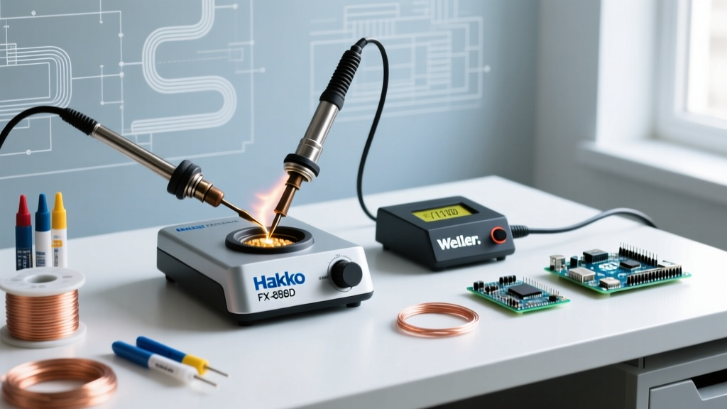
Before cutting a single inch of wire, you must calculate the target resistance. The power equation P = V² / R dictates your wire length and gauge. Most modern digital stations (like the Hakko FX-888D or Weller WE1010NA) use a 24V AC secondary transformer for safety, while older or direct-mains irons (like the Weller SP80) run on 120V AC.
| Station Type | Target Wattage | Voltage | Required Resistance (Ω) | Recommended AWG (Nichrome 80) | Approx. Wire Length Needed |
|---|---|---|---|---|---|
| 24V PID Station (e.g., Hakko FX-888D) | 65W | 24V AC | 8.86 Ω | 28 AWG (6.53 Ω/ft) | 1.35 ft (16.2 inches) |
| 24V PID Station (e.g., Weller WE1010) | 70W | 24V AC | 8.22 Ω | 28 AWG (6.53 Ω/ft) | 1.25 ft (15.0 inches) |
| 120V Direct Mains Iron | 40W | 120V AC | 360.0 Ω | 34 AWG (25.95 Ω/ft) | 13.87 ft (166 inches) |
Note: Resistance values for Nichrome 80 are based on standard annealed specifications at 20°C. As of 2026, a 1lb spool of high-purity 28 AWG Nichrome 80 costs between $35 and $45 from industrial suppliers like Temco Industrial.
Step-by-Step Winding Procedure
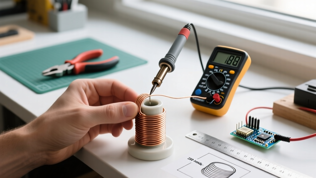
Winding the element requires precision. If the coils touch, they create a short circuit, bypassing the resistance and tripping your station's internal fuse. If the coils are too far apart, the ceramic core will develop uneven thermal gradients, leading to inaccurate thermocouple readings.
1. Core Preparation and Insulation
Modern elements use a high-alumina ceramic tube (typically 4mm outer diameter, 2mm inner diameter). Avoid older mica-sheet wrapped cores if possible; mica delaminates over time and poses inhalation risks if machined or sanded. Clean the ceramic core with isopropyl alcohol to remove machining oils that could carbonize and cause surface tracking.
2. Calculating the Pitch
For a 65W / 24V element using 28 AWG wire, you need roughly 16.2 inches of wire. If your ceramic core has a 4mm (0.157") diameter, the circumference is approximately 0.49 inches. Dividing 16.2 inches by 0.49 inches yields 33 total turns. If your winding zone on the ceramic core is 1.2 inches long, you must maintain a pitch of roughly 27.5 turns per inch. Because 28 AWG wire has a bare diameter of 0.0126 inches, a 27.5 TPI pitch leaves a microscopic air gap between coils, which is perfect for preventing shorts while ensuring uniform heat transfer.
3. Tension and Termination
Anchor the starting end of the wire using a high-temperature nickel crimp. Never use copper crimps or solder at the termination points; copper oxidizes rapidly above 300°C, and standard tin/lead or SAC305 solder will melt during the iron's initial burn-in. Apply consistent tension using a felt pad to ensure the wire bites slightly into the ceramic surface, preventing coil migration during thermal expansion.
Thermocouple Integration and Sensor Wrapping
The heating element is only half the system. The PID controller relies on a K-type thermocouple to regulate the nichrome wire's duty cycle. In composite elements (like the Hakko T18 or Weller RT series), the thermocouple is wound directly over the nichrome layer, separated by a secondary inner ceramic sleeve or high-temperature fiberglass sleeving.
Critical Safety Warning: Ensure a minimum dielectric isolation rating of 1.5kV between the nichrome heating coil and the K-type thermocouple junction. A short between the heater and the sensor will feed 24V AC directly into the station's low-voltage ADC (Analog-to-Digital Converter), instantly destroying the mainboard's microcontroller and op-amps.
When wrapping the K-type sensor wire, use Omega Engineering's high-temperature ceramic bead insulation or Nextel braided sleeving to protect the sensor leads from abrading against the nichrome windings during tip insertion and removal.
Digital PID Calibration: Closing the Loop
Once the physical element is rebuilt and installed, the station's internal PID algorithm must be calibrated to account for the new element's thermal mass and resistance tolerances. Factory nichrome wire has a tolerance of ±5%, which translates to a temperature offset of up to 15°C at the tip.
Calibrating a Hakko FX-888D (2026 Firmware Revision)
- Enter Calibration Mode: Power off the station. Press and hold the UP arrow button, then turn the power switch ON. Release the UP button when the display shows
*1. - Access Temperature Offset: Press ENTER. The display will show the current offset value (usually
000). - Measure Actual Tip Temp: Use a high-accuracy tip thermometer (e.g., Hakko FG-100B) with a surface K-type probe. Apply a dab of thermal paste to the probe and press it firmly against the flat face of a chisel tip.
- Adjust the Offset: If the station reads 350°C but the FG-100B reads 342°C, use the UP/DOWN arrows to input an offset of
+008. - Save and Reboot: Press ENTER to save. Power cycle the station. Allow 3 minutes for the thermal mass to stabilize, then re-verify.
For stations lacking digital menus, you will need to open the chassis and adjust the multi-turn cermet potentiometer (usually labeled VR1 or CAL) on the main PCB while monitoring the tip temperature. Refer to the official Hakko Calibration Guide for specific board layouts.
Failure Modes and Edge Case Troubleshooting
Even with perfect math, custom-wound nichrome elements can fail if environmental factors are ignored. Here are the most common edge cases encountered in the field:
- Hotspotting and Core Cracking: If the wire tension is too loose, the coils will bunch up near the termination points. This creates localized hotspots that exceed the 1000°C melting point of the nichrome, vaporizing the wire and cracking the alumina core due to thermal shock. Fix: Maintain strict, measured tension during the wind.
- Barrel Shorting: If the element is inserted into a stainless steel barrel without a high-temperature silicone or ceramic spacer, the expanded nichrome coils can touch the grounded metal barrel. This will trip the GFCI breaker on your workbench or blow the station's internal 2A glass fuse. Fix: Always use a crushed ceramic bead or high-temp Kapton tape wrap on the exterior of the element assembly.
- PID Oscillation (Hunting): If the thermocouple is placed too far from the nichrome windings, the PID controller will overcompensate, causing the tip temperature to swing ±20°C. Fix: Ensure the thermocouple junction is positioned within 2mm of the primary heating zone, directly beneath where the soldering tip's internal ferrule sits.
Final Burn-In and Oxidation Sealing
Before putting a rewound element into active duty, it requires a controlled burn-in to form the protective chromium oxide layer. Set the station to 250°C and let it run in open air for 20 minutes. The wire will transition from a bright metallic silver to a dull, matte gray. Do not exceed 300°C during this initial phase, as rapid oxidation before the protective layer forms will weaken the wire's structural integrity. Once the matte gray patina is uniform, your nichrome element is fully passivated, calibrated, and ready for precision SMD and through-hole soldering tasks.