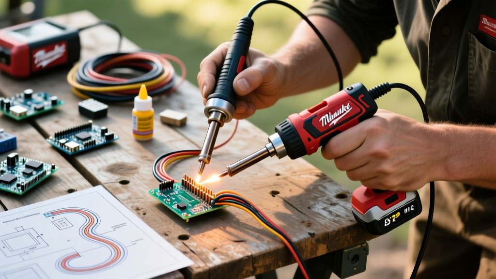

The Shift to Cordless: Why the M12 Platform Changes Field Work
For decades, field electricians, automotive technicians, and HVAC specialists relied on butane-powered irons or cumbersome power inverters to solder joints outside the workshop. The introduction of the Milwaukee M12 Cordless Soldering Iron (Model 48-22-6800) disrupted this paradigm, offering bench-top thermal recovery in a completely untethered form factor. As of 2026, this tool remains the benchmark for heavy-duty portable soldering, but its unique power delivery system requires specific techniques to maximize joint integrity.
Unlike a traditional 60W AC bench station that draws continuous, stable current, a cordless iron relies on a lithium-ion battery management system (BMS) to regulate voltage under heavy thermal loads. Mastering the m12 soldering iron milwaukee ecosystem means understanding the intersection of battery discharge curves, thermal mass, and flux chemistry. This technique guide will walk you through advanced field soldering methodologies, ensuring your off-bench joints meet rigorous industry standards.
Tool Anatomy and Thermal Dynamics
The Milwaukee 48-22-6800 features a digital LCD interface, a lock-off trigger for safety, and a ceramic heating element capable of reaching 800°F (426°C) in under 60 seconds. However, the rated 90W peak output is heavily dependent on the battery's ability to sustain voltage without triggering the BMS thermal cutoff.
Expert Insight: The iron's digital temperature readout measures the sensor near the heating element, not the absolute tip temperature. When touching a high-thermal-mass conductor like 10 AWG copper, the tip temperature will drop significantly before the sensor registers the loss and pulses the heater. Always pre-tin heavy wires to bridge this thermal gap.
M12 Battery Selection Matrix for Soldering
Choosing the right M12 REDLITHIUM battery is critical. A larger battery provides more runtime and better voltage stability under load, but it drastically alters the tool's center of gravity, leading to hand fatigue during precision PCB work.
| Battery Model | Capacity | Weight | Voltage Sag Under 90W Load | Best Application |
|---|---|---|---|---|
| M12 CP2.0 | 2.0Ah | 0.4 lbs | High (Drops to ~10.8V quickly) | Quick PCB repairs, small gauge signal wires |
| M12 XC4.0 | 4.0Ah | 0.7 lbs | Moderate (Maintains ~11.2V) | General automotive wiring, 14-18 AWG splices |
| M12 HIGH OUTPUT 5.0Ah | 5.0Ah | 0.9 lbs | Minimal (Sustains 11.8V+) | Heavy gauge (10-12 AWG), cold environment soldering |
Temperature Profiling for Field Environments
Field environments rarely offer the controlled 72°F ambient temperature of a laboratory. When soldering in unheated garages or outdoor enclosures, the ambient copper acts as a massive heat sink. According to the IPC J-STD-001 standards for soldered electrical assemblies, proper wetting requires the base metal to reach the solder's liquidus temperature plus an additional 40°C to 50°C for optimal capillary action.
Wire Gauge vs. Target Temperature Matrix
| Wire Gauge (AWG) | Target Iron Temp | Dwell Time Limit | Recommended Flux Core |
|---|---|---|---|
| 22 - 26 AWG (Signal) | 600°F (315°C) | 2 - 3 Seconds | Sn63/Pb37 Rosin (RA) |
| 16 - 18 AWG (Power) | 700°F (371°C) | 3 - 5 Seconds | Sn60/Pb40 Mildly Activated |
| 10 - 12 AWG (Heavy) | 780°F - 800°F | 5 - 8 Seconds | Sn99.3/Cu0.7 (Lead-Free) + External Paste |
Note: When using lead-free alloys like Sn99.3/Cu0.7 in the field, the higher melting point (441°F) demands maximum iron temperature and aggressive external flux application to prevent cold joints.
Step-by-Step: Soldering 12 AWG Automotive Wiring in the Cold
Splicing heavy-gauge wiring in cold environments is where the Milwaukee M12 soldering iron proves its worth over butane alternatives. Butane irons struggle to maintain tip temperature when pressed against thick copper. Here is the definitive technique for a bulletproof 12 AWG splice using the 48-22-6800.
- Mechanical Preparation: Strip 3/4 inch of insulation from both wire ends. Per NFPA 70 (National Electrical Code) best practices for signal and low-voltage splicing, create a mechanical Western Union (Lineman's) splice first. The solder should never bear the mechanical tensile load.
- External Flux Application: In cold environments, the rosin core inside your solder wire will activate too slowly. Apply a small dab of high-quality tack flux (e.g., Amtech or Chip Quik) directly to the twisted copper joint before applying heat.
- Pre-Heat the Mass: Set the M12 iron to 800°F. Equip a wide chisel tip (Milwaukee 48-22-9002 or equivalent). Press the flat side of the chisel tip against the thickest part of the splice for 3 seconds to allow the copper to absorb the thermal energy.
- Feed the Solder: Do not melt the solder on the iron tip and carry it to the joint (this burns off the flux). Instead, keep the iron on the copper wire and feed the solder wire directly into the junction where the tip meets the copper. Capillary action will draw the molten solder through the splice.
- Visual Inspection: A proper joint will exhibit a smooth, concave fillet with a shiny finish (for leaded) or a slightly dull, satin finish (for lead-free). If the solder balls up and refuses to flow into the strands, remove heat immediately, let it cool, add more flux, and re-apply.
Common Failure Modes and Troubleshooting
Even with premium cordless equipment, field conditions introduce variables that can compromise joint integrity. Recognizing these failure modes is critical for any technician.
- Battery Thermal Cutoff Mid-Joint: If you are holding the trigger down continuously for over 45 seconds on a high-temperature setting, the M12 BMS may cut power to protect the cells. Solution: Use the lock-off button to keep the iron engaged, but lift the tip off the workpiece for 2-second intervals to allow the battery to cool microscopically while the ceramic element retains heat.
- Tip Oxidation (The "Black Death"): Leaving the iron at 800°F while not actively soldering causes rapid tip oxidation, especially in humid outdoor environments. Once oxidized, the tip will not transfer heat or accept solder. Solution: Always dial the temperature back to 400°F during idle periods and keep a damp cellulose sponge or brass wool shavings in your tackle box for immediate tip cleaning.
- Cold Joints on High-Vibration Harnesses: A cold joint looks grainy and cracked. In automotive applications, this will inevitably fail due to engine vibration. This usually occurs when the technician moves the wire before the solder has fully transitioned from the plastic state to the solid state. Solution: Hold the wire completely still for 4 seconds after removing the iron.
Maintenance: Prolonging Tip Life Off the Bench
Bench stations have auto-sleep features; field irons rely on user discipline. The replacement tips for the Milwaukee M12 iron (typically priced around $15-$20 each in 2026) are an ongoing consumable cost. To maximize their lifespan, always "tin the tip before holstering." Before turning the tool off, melt a generous amount of rosin-core solder over the entire working surface of the tip. This sacrificial layer of solder will oxidize instead of the iron plating underneath. When you power the tool on for the next job, simply wipe the sacrificial solder off on your brass wool, and you will be left with a pristine, highly conductive tip surface.
Final Thoughts on Cordless Soldering
The m12 soldering iron milwaukee setup is not merely a convenience tool; when paired with the correct battery and thermal techniques, it is a professional-grade instrument capable of executing mission-critical splices in the most unforgiving environments. By respecting the thermal dynamics of lithium-ion power delivery and adhering to strict flux and temperature protocols, you can achieve bench-quality results anywhere your work takes you.