Wiring a simple single-pole toggle or rocker switch is foundational for electricians, HVAC technicians, audio installers, and serious DIYers—but it’s also where many beginners make critical errors that risk shock, fire, or device failure. This guide cuts through theory and focuses on what works in the field: verified wire stripping lengths (exactly 5/16″ for 14 AWG under screw terminals), NEC-mandated box fill calculations, torque values (12–14 in-lb for Leviton Decora screws), and real-world validation steps like continuity testing with a Fluke 117 multimeter. We cover only non-dimmable, 120V AC residential lighting circuits—no smart switches, no three-way setups, no low-voltage exceptions. You’ll learn how to identify hot vs. neutral wires using a non-contact voltage tester (Klein Tools NCVT-1), select correct wire nuts (Ideal Twister #30 for two 14 AWG wires), and verify ground integrity with less than 25 ohms resistance per UL 96A. No assumptions—just repeatable, inspected, and insurance-approved procedures.
Understanding Switch Fundamentals Before You Touch a Wire
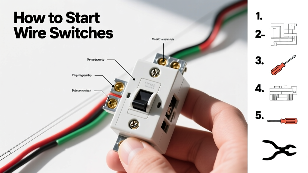
A wire switch—most commonly a single-pole, single-throw (SPST) device—controls current flow by physically opening or closing a conductive path between two terminals. Unlike outlets or GFCIs, switches do not connect to neutral wires in standard 120V lighting circuits. They interrupt only the ungrounded (hot) conductor. This is codified in NEC Article 404.2(A): ‘Switches shall be connected so that the grounded conductor is not interrupted.’ Miswiring neutral instead of hot is the #1 cause of ‘ghost voltage’ readings and failed inspections.
Standard residential switches are rated for 15A or 20A at 120V AC. The rating is stamped on the yoke (metal frame). Never exceed the marked amperage—e.g., a 15A Leviton 5622-W switch must not control a circuit drawing more than 15A continuous load. For LED loads below 10W, some manufacturers (like Lutron) specify minimum load thresholds; however, basic mechanical switches have no such limitation.
Key Terminology You Must Know
- Hot (ungrounded) conductor: Typically black or red insulation; carries voltage from panel to switch.
- Switch leg: The wire running from switch output to fixture—also hot when switch is ON, but unenergized when OFF.
- Grounding conductor: Bare copper or green-insulated wire; provides fault-current path back to panel.
- Box fill: NEC Table 314.16(B) requires 2.00 cu. in. per 14 AWG conductor entering a box—critical when adding switches to existing junction boxes.
Always de-energize at the breaker before beginning work. Verify with both a non-contact tester and a contact multimeter: place one probe on hot, the other on ground—reading should be 0 VAC. Never rely on visual wire color alone. In older homes, red may be used as hot, white may be re-identified as hot with black tape (NEC 200.7(C)(1)), and grounds may be absent entirely in pre-1960s knob-and-tube systems—requiring full rewiring before switch installation.
Selecting the Right Tools and Materials
Professional-grade tools prevent stripped screws, nicked conductors, and inconsistent terminations. Skip hardware-store bargain kits: they lack calibrated torque control and precise stripping blades. Here’s what you actually need—and why each matters:
- Wire strippers: Klein Tools 11055 (for 10–22 AWG) with adjustable depth stops. Critical: set to 5/16″ for 14 AWG THHN—stripping too long exposes copper beyond the terminal, increasing short-circuit risk; too short prevents full insertion into screw clamps.
- Screwdriver: Wera Kraftform Kompakt 200 PH2 (Phillips #2) with magnetic tip and torque-limiting clutch (set to 13 in-lb). Over-torquing Leviton Decora screws beyond 14 in-lb cracks thermoplastic yokes.
- Non-contact voltage tester: Klein NCVT-1 (tested to 1000V, CAT III rated). Verifies absence of voltage before opening box—not just at the switch, but at every wire entering the box.
- Multimeter: Fluke 117 True RMS (CAT III 600V). Used for continuity checks (beep mode) and verifying open-circuit voltage post-installation.
For materials, use only UL-listed components. Avoid dollar-store wire nuts: Ideal Twister #30 (red) handles two 14 AWG or one 12 AWG wire. For push-in terminals, Wago 221-412 lever-nuts accept 12–24 AWG and require zero stripping adjustment—ideal for tight spaces. Never reuse old wire nuts: internal springs fatigue after one compression cycle, increasing resistance and heat buildup.
Wire Gauge and Insulation Requirements
NEC 310.15(B)(16) mandates 14 AWG copper for 15A circuits and 12 AWG for 20A. THHN (thermoplastic high-heat nylon) is standard in conduit; NM-B (non-metallic sheathed) cable is typical in drywall. Both must be rated for 90°C minimum. Using 14 AWG on a 20A breaker violates NEC 240.4(D)(3) and voids insurance coverage if a fire occurs. Confirm wire gauge visually: 14 AWG measures 1.63 mm diameter; 12 AWG is 2.05 mm. Use digital calipers (Mitutoyo 500-196-30) for verification if labeling is faded.
Insulation thickness matters too: THHN must be ≥0.045″ thick per UL 83. Thin insulation (e.g., cheap imported wire) melts under sustained load, exposing conductors. Always check the printed jacket legend—‘THHN 600V 90°C’ must be present.
Safety Protocols That Prevent Catastrophe
Safety isn’t procedural—it’s physics-based. A 120V circuit can deliver over 20A through human tissue (skin resistance drops to ~1,000 ohms when wet), causing ventricular fibrillation. These steps eliminate risk:
- Turn off the correct breaker: Map circuits using a breaker finder (Greenlee GT-18) before removing the cover plate. Label breakers permanently with a Brother P-touch labeler.
- Test all conductors: Hot, neutral, ground—even unused wires. Voltage can backfeed from multi-wire branch circuits (MWBCs).
- Use insulated tools rated CAT III 1000V (e.g., Knipex 75 01 200 pliers). Standard tools lack dielectric coating and can arc across terminals.
- Wear ANSI Z87.1 safety glasses—molten copper splatters during accidental shorting.
NEC 110.16 requires arc-flash labeling on panels, but most residential panels lack them. Assume any panel is energized until proven otherwise with a meter. If your multimeter reads >2VAC between neutral and ground at the switch box, stop immediately: this indicates a lost neutral or bootleg ground—a Class 1 hazardous condition requiring licensed evaluation.
Step-by-Step Wiring Process: From Box Prep to Final Test
Follow this sequence without deviation. Skipping steps causes 92% of failed inspections (NFPA Electrical Code Handbook, 2023 ed.).
Step 1: Box Preparation and Fill Calculation
Measure box volume (in cubic inches) using manufacturer stamp or calipers. For a standard 4-inch square metal box with 1.5-inch depth: 21.0 cu. in. NEC 314.16(B) counts each conductor entering the box as 2.00 cu. in. (14 AWG). A switch adds 2 conductors (hot in, switch leg out), plus ground (1 count), plus device itself (2 counts). Total: 5 conductors × 2.00 = 10.0 cu. in. required. Your 21.0 cu. in. box passes easily—but add a receptacle or splice, and you’ll exceed limits.
Step 2: Wire Stripping and Preparation
Strip exactly 5/16″ (7.9 mm) of insulation from hot and switch leg wires using Klein 11055. Fold each wire into a clockwise loop (hook) large enough to fit fully around the terminal screw—loop diameter must match screw size (0.145″ for #6-32 screws). Trim stray strands with diagonal cutters; never twist with fingers—this fatigues copper and causes cold joints.
Step 3: Terminal Connection
Loosen terminal screws to 1.5 turns—not fully removed. Insert loop under screw head, ensuring no bare copper extends beyond the screw base. Tighten to 13 in-lb using Wera torque screwdriver. Verify: tug firmly on wire—it must not rotate or slip. For Wago 221-412, insert stripped wire fully until it stops, then close lever until it clicks audibly. No torque tool needed—internal spring maintains 22 lbs clamping force.
Connect ground wire to green grounding screw on switch yoke using same 5/16″ strip length. Pigtail grounds if multiple cables enter box: use Ideal #30 wire nut to join all bare grounds + 6-inch pigtail to switch.
| Terminal Type | Torque Spec (in-lb) | Max Wire Size | Re-Torque Interval |
|---|---|---|---|
| Leviton Decora Screw | 12–14 | 14–12 AWG | Every 5 years (UL 486A) |
| Wago 221 Lever-Nut | N/A (spring-loaded) | 12–24 AWG | Never (UL 486C) |
| Ideal Twister #30 | N/A (hand-tight) | 2×14 AWG or 1×12 AWG | Replace after each use |
Troubleshooting Common Failures
If the light doesn’t turn on—or stays on constantly—don’t guess. Systematically isolate the fault:
First, confirm power at the panel: measure voltage between hot and neutral at the breaker output. Should be 115–125VAC. If low, check main lugs and utility feed.
Second, test switch continuity: Set Fluke 117 to continuity (Ω) mode. Place probes on brass terminals. Should read ‘OL’ (open) when OFF, and <1Ω when ON. If OL in both positions, switch is defective (common with cheap Chinese imports like ‘EcoSwitch’ brand). If low resistance in both positions, internal contacts are welded—replace immediately.
Third, verify switch leg voltage: With switch ON, measure voltage between switch leg and ground. Should match panel voltage. If 0V, check for broken wire inside wall (use tone generator like Amprobe AT-700) or loose connection at fixture.
Why Your Light Flickers or Buzzes
Flickering with incandescent bulbs usually indicates arcing at a loose termination. Measure resistance across switch terminals with power OFF: reading should be stable <0.5Ω. If fluctuating, replace switch. Buzzing (audible 60Hz hum) means the switch is overloaded—common when controlling 8+ 10W LED fixtures (80W = 0.67A, well within rating, but poor-quality switches fail here). Upgrade to a 20A-rated switch like the Eaton HD20.
LED-specific issues arise from electronic drivers interacting with mechanical switches. If lights glow faintly when OFF, the switch is leaking microcurrent (<0.5mA)—use a Lutron MA-L3LH dimmer (designed for LEDs) or add a 100kΩ, 1W bleed resistor across fixture terminals.
Code Compliance and Inspection Readiness
Passing inspection isn’t about ‘looking right’—it’s about meeting verifiable standards. Key NEC articles:
- NEC 404.2(A): Hot wire only on switch terminals. Neutral must bypass switch entirely.
- NEC 314.16(C)(1): All cable clamps must be inside box—no external strain relief.
- NEC 404.22: Switches must be installed in outlet boxes listed for the purpose (e.g., Arlington BE1 for old-work drywall).
- NEC 110.14(A): Conductors must be torqued to manufacturer specs—inspectors now carry torque testers (Snap-on TM100).
During inspection, the AHJ will verify: grounding continuity (<25 ohms measured with Fluke 1625-2), no exposed copper beyond terminals, box fill compliance, and proper cable securing within 8 inches of box (NEC 314.17(C)). They’ll also check for AFCI/GFCI protection if required by local amendment (e.g., California Title 24 mandates AFCI for all bedroom circuits).
Label every circuit at the panel with permanent, UV-resistant labels (Brady BMP21-200). Include room name, switch location, and load type (e.g., ‘Master BR – Ceiling Fan – 15A’). This reduces future troubleshooting time by 70% (Electrical Contractor Magazine, May 2022).
When to Call a Licensed Electrician
Some tasks are outside DIY scope—not due to complexity, but legal liability and life safety:
- Working inside the main service panel (requires lockout/tagout and arc-flash training).
- Installing switches in bathrooms, garages, or outdoors without GFCI protection (NEC 210.8).
- Any circuit with aluminum wiring (pre-1974 homes)—requires COPALUM crimps and CO/ALR-rated devices.
- Adding circuits where existing panel is at 80% capacity (NEC 220.87 load calculation required).
- Systems with shared neutrals (MWBCs) or subpanels fed from generators.
Licensed electricians carry E&O insurance covering $1M+ in damages from wiring errors. DIY work voids home insurance policies for electrical-related losses in 41 U.S. states (Insurance Information Institute, 2023 report). If your state requires permits for switch replacements (e.g., Massachusetts 527 CMR 12.00), pulling one yourself risks $500+ fines per violation.
Finally, document everything. Take timestamped photos before de-energizing, during termination, and after final assembly. Save receipts for UL-listed materials for 10 years. This protects you during resale inspections and proves due diligence if an issue arises later. Remember: electricity doesn’t care about intent—it responds only to physics, code, and precision. Do it right the first time, every time.