
The Convective Heat Transfer Reality of SMD Rework
Unlike a traditional contact soldering iron that relies on conductive heat transfer through a copper tip, a hot air soldering station utilizes convective heat transfer. Air is inherently a poor thermal conductor compared to solid metals. Therefore, the temperature displayed on your station's LCD is largely meaningless without accounting for airflow volume (measured in liters per minute, or L/min) and nozzle proximity. A reading of 350°C at 20 L/min will barely melt Sn63/Pb37 solder on a large ground plane, while 350°C at 100 L/min focused through a 4mm nozzle will instantly scorch a PCB's FR4 substrate and lift copper pads.
Professional rework requires managing the thermal mass of the entire component and its underlying copper traces. According to the IPC-7711/7721 Rework Standard, successful surface mount device (SMD) rework hinges on achieving a uniform thermal profile across all solder joints simultaneously. If one corner of a QFP-64 (Quad Flat Package) reaches the liquidus temperature before the opposite corner, surface tension differentials will cause the component to skew or 'tombstone' as the molten solder seeks equilibrium.
Expert Insight: Never rely solely on the station's temperature dial. The actual temperature at the solder joint is a function of ambient room temperature, board thickness (e.g., 1.6mm vs 3.2mm), internal copper layer count, and the specific heat capacity of the component's epoxy body. Always use an external K-type thermocouple taped to a dummy board to map your specific station's thermal output before working on mission-critical assemblies.
2026 Station Comparison Matrix: Prosumer vs. Industrial
Choosing the right equipment dictates your success rate with complex packages like BGAs (Ball Grid Arrays) and dense 0402 passives. Below is a technical comparison of three dominant hot air soldering station architectures currently defining the market.
| Model | Wattage / Max Temp | Airflow (L/min) | Heater Architecture | Estimated Price (USD) | Best Application |
|---|---|---|---|---|---|
| Quick 861DW | 1000W / 500°C | 120 L/min | Ceramic Core / Spiral | $260 - $290 | General SMD, QFP, SOIC, Connector removal |
| Hakko FR-810B | 650W / 480°C | 50 L/min (per head) | Cartridge / Induction | $650 - $750 | Precision 0402/0201 passives, delicate flex-PCBs |
| JBC JTSE-2B | 1300W / 450°C | 150 L/min | Smart Cartridge (Integrated) | $1,400 - $1,550 | Heavy thermal mass, multi-layer server boards, BGA |
The Quick 861DW remains the undisputed king of the prosumer bench. Its 1000W ceramic heater and brushless fan provide massive thermal recovery, essential for desoldering USB-C connectors anchored to large ground pours. However, its minimum airflow setting can still be too aggressive for 0201 resistors, often blowing them off the pads. Conversely, the Hakko FR-810B offers unparalleled airflow precision, allowing technicians to work on micro-SMDs without displacement, though it struggles with heavy copper pours on 6-layer boards without external preheating.
The 5-Step Protocol for High-Pin-Count QFP Extraction
Removing a 144-pin QFP microcontroller without cratering the underlying BGA pads requires strict adherence to thermal soaking and mechanical restraint. Follow this exact sequence:
- Moisture Baking (Prevent Popcorning): ICs absorb ambient moisture. When exposed to 250°C+ hot air, this moisture vaporizes, expanding and cracking the silicon die or delaminating the package (the 'popcorn' effect). Bake the PCB at 125°C in a convection oven for 4 to 8 hours prior to rework.
- Flux Application: Apply a high-tack, no-clean gel flux (e.g., Amtech NC-559-V2-TF or Chip Quik SMD291AX) to all four pin arrays. Tack flux serves a dual purpose: it lowers the surface tension of the solder for uniform wetting and acts as a mild thermal adhesive to keep the IC seated while the joints melt.
- Nozzle Selection & Positioning: Select a square nozzle that matches the IC's plastic body size, not the pin-to-pin span. For a 14x14mm body, use a 15x15mm nozzle. This ensures the hot air reflects off the IC body and washes down over the pins, rather than blasting directly onto the fragile FR4 pads.
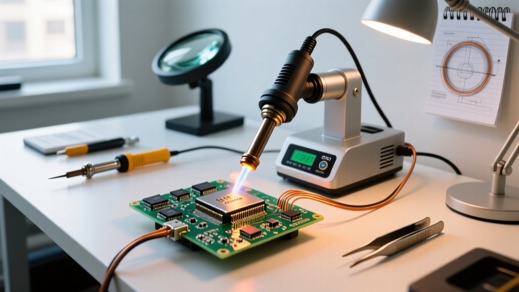
- The Thermal Soak Sequence: Set the station to 340°C (for leaded solder) or 380°C (for SAC305 lead-free). Begin hovering 50mm above the board in a continuous circular motion for 30 seconds to pre-heat the local area. Drop to 10mm above the IC and continue the circular motion. Do not hold the nozzle static; stationary air will scorch the epoxy.
- Vacuum Extraction: Once the solder flashes to a liquid state (usually 45-60 seconds at close range), engage a vacuum pickup pen. Never use metal tweezers to pry or lift the chip. Z-axis mechanical stress on molten solder joints will tear the copper annular rings right off the fiberglass substrate, causing irreversible pad cratering.
Failure Mode Analysis: Diagnosing Rework Disasters
When a rework operation fails, the physical evidence left on the PCB tells a specific story. Recognizing these failure modes allows you to adjust your hot air parameters dynamically.
- Pad Cratering / Lifting: Cause: Mechanical force applied before the solder fully reached liquidus, or excessive localized heat degrading the FR4 resin's glass transition temperature (Tg). Fix: Increase airflow rather than temperature to penetrate the thermal mass faster, and use a vacuum pen for extraction.
- Solder Bridging (Shorts): Cause: Insufficient flux activation or removing the heat source too abruptly, causing the solder to freeze before surface tension can pull it apart. Fix: Add more gel flux and perform a secondary 'reflow pass' with the hot air station set to 50 L/min to allow the flux to break the oxide layers and separate the bridges.
- Component Discoloration / Scorching: Cause: Airflow volume too low, forcing the technician to leave the nozzle in one place too long to achieve melting temperatures. Fix: Increase L/min to deliver higher convective energy, allowing for faster, broader heating.
- Tombstoning (Drawbridging): Cause: Asymmetric heating on small passives (0603, 0402). One pad melts before the other, and the surface tension of the molten solder pulls the component upright. Fix: Use a wider nozzle and increase the hover height to create a larger, more uniform thermal envelope over the entire component.
Fume Extraction and Respiratory Safety
The vaporization of rosin-based and synthetic fluxes generates colophony and complex aliphatic aldehydes. These are potent respiratory sensitizers linked to occupational asthma. According to NIOSH guidelines on soldering fumes, standard bench fans that simply blow air away from the technician's face are entirely inadequate and actually increase the dispersion of sub-micron particulates across the laboratory.
A proper hot air rework setup requires a localized exhaust ventilation (LEV) system. The extraction arm must be positioned within 150mm (6 inches) of the rework site, capturing the plume at the source. Furthermore, the filtration unit must utilize a multi-stage setup: a pre-filter for large particulates, a true HEPA filter for sub-micron aerosolized flux residues, and an activated carbon bed (minimum 2kg of carbon) to adsorb volatile organic compounds (VOCs). Replacing these filters every 6 months is non-negotiable for maintaining respiratory safety.
Advanced Scenarios: RF Shields and Ground Plane Anchors
Removing Soldered RF Shields
RF shielding cans are typically soldered with a continuous perimeter joint directly to a massive ground plane. A standard hot air soldering station will struggle to heat the entire perimeter simultaneously. The Expert Technique: Use a wide rectangular nozzle (e.g., 30x30mm) and set the airflow to maximum (100+ L/min) at 380°C. Apply copious amounts of liquid flux along the seams. Heat one corner until it flows, insert a dental pick to hold it up, and 'walk' the pick around the perimeter as you follow with the hot air nozzle. Alternatively, use a low-temperature solder alloy like Chip Quik (Sn42/Bi57, melting at 138°C) to dilute the factory lead-free solder, drastically lowering the thermal threshold required for removal.
BGA Rework Limitations
While a high-end hot air station can technically reflow a BGA, blind reflow without optical alignment or targeted bottom-side preheating yields a high defect rate. The outer rows of BGA balls will reach liquidus long before the inner thermal pads. For reliable BGA replacement, a hot air station should only be used for the removal phase. Installation requires a dedicated BGA rework station with split-vision optics and programmable multi-zone thermal profiling to ensure the delta-T (temperature difference) across the die remains below 5°C during the critical reflow phase.