
Introduction to the Hakko FX-888D Platform
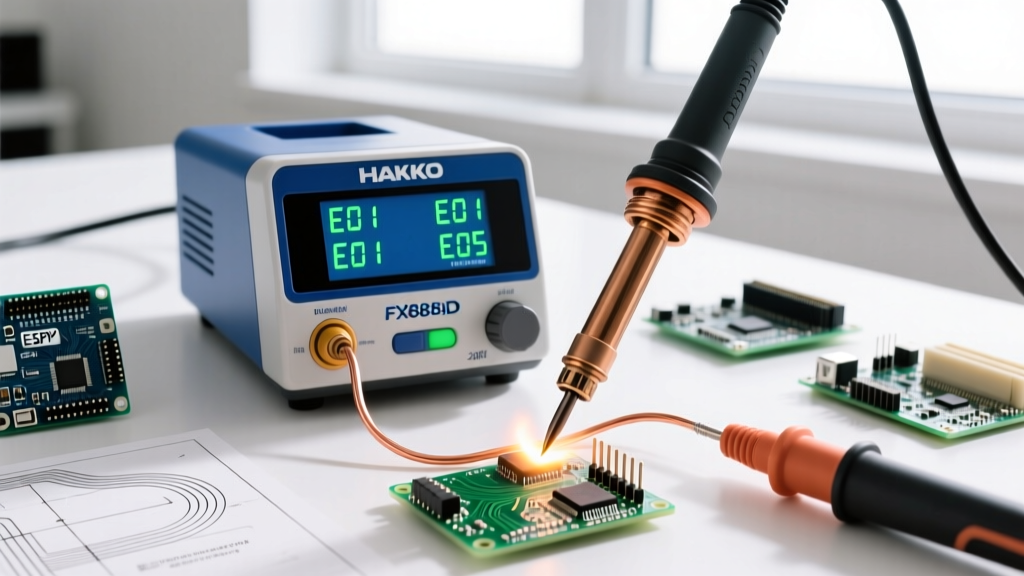
The Hakko FX-888D has maintained its status as the gold standard for both professional electronics repair labs and advanced DIY workbenches well into 2026. Renowned for its robust 70W ceramic heating element, closed-loop PID temperature control, and extensive T18 tip ecosystem, this station is a workhorse. When sourcing equipment, technicians often encounter the Hakko FX888D 23BY digital soldering station FX 888D SKU. The "23BY" designation typically refers to specific distributor bundles or regional packaging variants that may include supplementary T18-B chisel tips, a brass wool sponge, or a localized power cord configuration. However, the internal architecture, firmware, and core electronics remain identical to the standard North American 120V FX 888D model.
Despite its legendary reliability, continuous use in high-volume environments or improper maintenance can lead to thermal drift, sensor failures, and error codes. This comprehensive troubleshooting and maintenance guide will walk you through advanced diagnostics, multimeter testing, digital calibration, and component-level repairs to keep your station operating within the strict thermal tolerances required by modern electronics assembly standards.
Multimeter Diagnostics: Testing the 5-Pin Handpiece
Before opening the main station chassis, you must isolate whether a fault lies within the handpiece, the flexible silicone cord, or the station's internal PCB. The FX-888D handpiece connects via a standard 5-pin DIN connector. Using a digital multimeter (DMM) set to the Ohms (Ω) range, you can verify the integrity of the internal Hakko B1321 ceramic heating element and the integrated thermocouple.
Disconnect the handpiece from the station and probe the male pins on the handpiece connector. Refer to the diagnostic matrix below for expected readings at room temperature (approx. 20°C to 25°C):
| Measurement Target | DIN Pins | Expected Resistance (Ω) | Failure Indication |
|---|---|---|---|
| Ceramic Heater Element | Pin 1 & Pin 2 | 13.0Ω - 16.0Ω | Open circuit (OL) indicates a snapped heater wire or broken cord. |
| Thermocouple Sensor | Pin 3 & Pin 4 | 2.0Ω - 4.0Ω | OL or 0.0Ω indicates a failed sensor junction inside the B1321. |
| ESD Ground Continuity | Pin 5 to Tip Barrel | < 2.0Ω | Resistance > 2Ω indicates oxidation or a broken ground wire. |
Expert Tip: Flex the silicone cord near the strain relief while monitoring the DMM. Intermittent jumps to "OL" (Open Loop) confirm internal copper fatigue, which is the leading cause of intermittent H-E errors. Replacement cords (Hakko part # B3251) retail for approximately $18 in 2026 and are a straightforward solder-and-solder-sleeve repair if you are comfortable with wire splicing.
Decoding and Resolving H-E and S-E Error Codes
The FX-888D's digital display is designed to halt heating immediately if it detects a critical hardware anomaly, protecting both the workpiece and the station's internal triac from thermal runaway.
The H-E (Heater Error) Code
An H-E code signifies that the station's microcontroller is not detecting the expected resistance across the heater circuit.
- Step 1: Verify the handpiece using the Pin 1 & 2 multimeter test outlined above.
- Step 2: If the handpiece tests perfectly, the fault lies in the station. Unplug the unit, open the chassis (removing the four recessed Phillips screws), and inspect the 5-pin DIN receptacle soldered to the main PCB.
- Step 3: Look for cold solder joints or flux creep on the DIN pins. Reflow these joints with a secondary iron if necessary. If the PCB traces are intact and the cord is verified, the internal triac or optocoupler on the mainboard may have failed, necessitating a full station replacement (approx. $125 USD).
The S-E (Sensor Error) Code
An S-E code indicates a short or open circuit in the thermocouple feedback loop (Pins 3 & 4). Because the thermocouple is embedded deep within the ceramic B1321 heater, an S-E error almost always requires replacing the entire heating element assembly. Attempting to extract the thermocouple from the ceramic core will shatter it. A genuine Hakko B1321 replacement heater costs around $28 and takes less than three minutes to swap using a small Phillips screwdriver to remove the T18 tip and locking sleeve.
Step-by-Step Digital Temperature Calibration
Over time, thermal lag and tip degradation can cause a discrepancy between the digital display and the actual temperature at the tip's working face. According to the IPC J-STD-001 Standard for soldered electrical and electronic assemblies, maintaining documented thermal accuracy is critical for preventing cold solder joints or thermal damage to sensitive SMD components. To calibrate your FX 888D, you will need a dedicated tip thermometer (such as the Hakko 191 or FG-100B).
- Enter Service Mode: Turn the station power switch OFF. Press and hold the UP arrow button. While holding UP, turn the power switch ON.
- Input Password: The display will show "000". This is the default factory password. Press the ENTER button to proceed. (If the password was changed by a previous technician, a hard reset by removing the internal CMOS battery for 5 minutes will restore it to 000).
- Measure Actual Temperature: Insert a fresh, pre-tinned T18-B tip. Set the station to 350°C (662°F). Allow it to stabilize for 3 minutes. Apply a small blob of solder to the tip thermometer's sensor and place it against the working face of the T18 tip.
- Adjust the Offset: If the tip thermometer reads 342°C (an 8-degree deficit), use the UP/DOWN arrows on the FX-888D to adjust the internal offset value by +8.
- Save and Exit: Press ENTER to save the calibration data to the EEPROM, then power cycle the station.
Advanced Tip Maintenance and Oxidation Recovery
The T18 series tips feature an iron plating over a copper core. Once this iron layer is compromised or heavily oxidized, heat transfer efficiency plummets, forcing the PID controller to run the 70W heater at 100% duty cycle, which degrades the B1321 ceramic element prematurely.
Critical Warning: Never use sandpaper, files, or abrasive scouring pads on T18 tips. Removing the microscopic iron plating exposes the copper core, which will rapidly dissolve into molten solder, ruining the tip in minutes and potentially contaminating your PCB pads with copper inclusions.
Oxidation Recovery Protocol: If your tip has turned black and refuses to wet with solder, do not simply turn up the heat. Instead, utilize a chemical tip tinner (such as Hakko 599B or equivalent). 1. Set the station to a moderate 280°C. 2. Plunge the oxidized tip into the tip tinner compound for 3-5 seconds while twisting it gently. The mild phosphoric acid and solder powder will chemically strip the oxidation and re-tin the surface simultaneously. 3. Wipe the tip on a damp cellulose sponge or brass wool, then immediately apply a thick layer of high-quality 63/37 rosin-core solder to protect the iron plating from ambient oxygen.
ESD Grounding Verification for Sensitive ICs
When working with modern MOSFETs, microcontrollers, or RF modules, Electrostatic Discharge (ESD) protection is non-negotiable. The ANSI/ESD S20.20 standard outlines strict requirements for grounding soldering equipment. The FX-888D's 5-pin connector routes Pin 5 directly to the station's earth ground prong on the AC plug.
As part of your annual maintenance routine, use a milliohm meter to verify the resistance between the soldering tip and the earth ground pin on the station's AC power cord. This reading must remain below 2.0Ω. If resistance spikes, disassemble the handpiece handle and clean the internal brass grounding spring that makes contact with the rear of the B1321 heater assembly. A simple application of DeoxIT contact cleaner on this spring can restore perfect ESD continuity and save thousands of dollars in ruined silicon.
Teardown and Internal PCB Inspection
Unlike modern high-frequency switching soldering stations, the Hakko FX-888D utilizes a traditional, heavy laminated iron-core transformer. This design choice provides immense thermal inertia and exceptional recovery times but makes the unit susceptible to mechanical shock. If the station has been dropped, the transformer's mounting brackets can loosen, causing a 60Hz mechanical hum or, worse, chafing against the low-voltage secondary wiring.
During a teardown, inspect the main PCB for any signs of thermal stress. The triac (usually mounted on a small aluminum heatsink near the transformer) manages the AC switching for the heater. If the thermal paste between the triac and the heatsink has dried out and cracked, the triac may overheat and fail short, sending unregulated 24V AC directly to the handpiece—a catastrophic failure that will instantly melt the T18 tip and destroy the heater. Reapplying high-quality silicone thermal compound during a 5-year teardown is a highly recommended preventative measure.
Conclusion
Proper maintenance of your Hakko FX888D 23BY digital soldering station FX 888D ensures it will easily survive a decade of daily use. By mastering multimeter diagnostics, adhering to strict ESD grounding checks, and performing routine digital calibrations, you elevate your workbench from a hobbyist setup to a professional, IPC-compliant repair environment. Always rely on genuine Hakko replacement parts and consult the Hakko USA Support Portal for updated firmware schematics and safety bulletins.