
Introduction: Beyond the Metal Stick
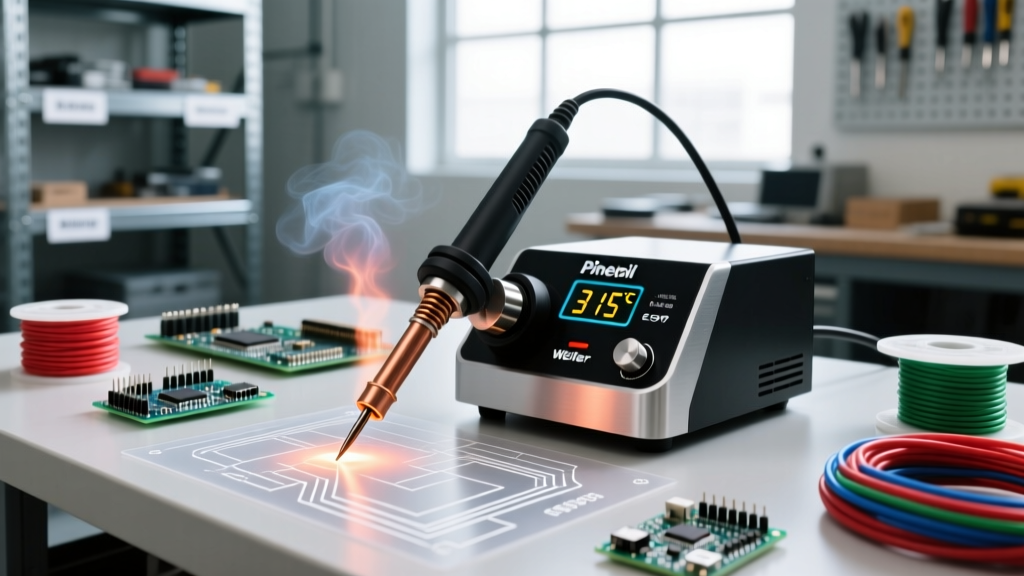
To the untrained eye, a soldering iron is a simple heated metal stick. However, modern electronics assembly requires precise thermal management, especially when working with sensitive surface-mount devices (SMDs) or high-thermal-mass through-hole components. Understanding the specific parts of the soldering iron is not just an academic exercise; it is a critical troubleshooting skill. When a joint turns cold, a tip blackens, or a station throws an error code, knowing the internal anatomy allows you to isolate the failure point—whether it is a degraded thermocouple, a dissolved iron plating layer, or a failing ceramic heater.
In this deep dive, we deconstruct the modern soldering iron assembly, examining the metallurgy, electronics, and mechanical engineering that make precision soldering possible in 2026.
The Handle and Chassis: Ergonomics and Thermal Isolation
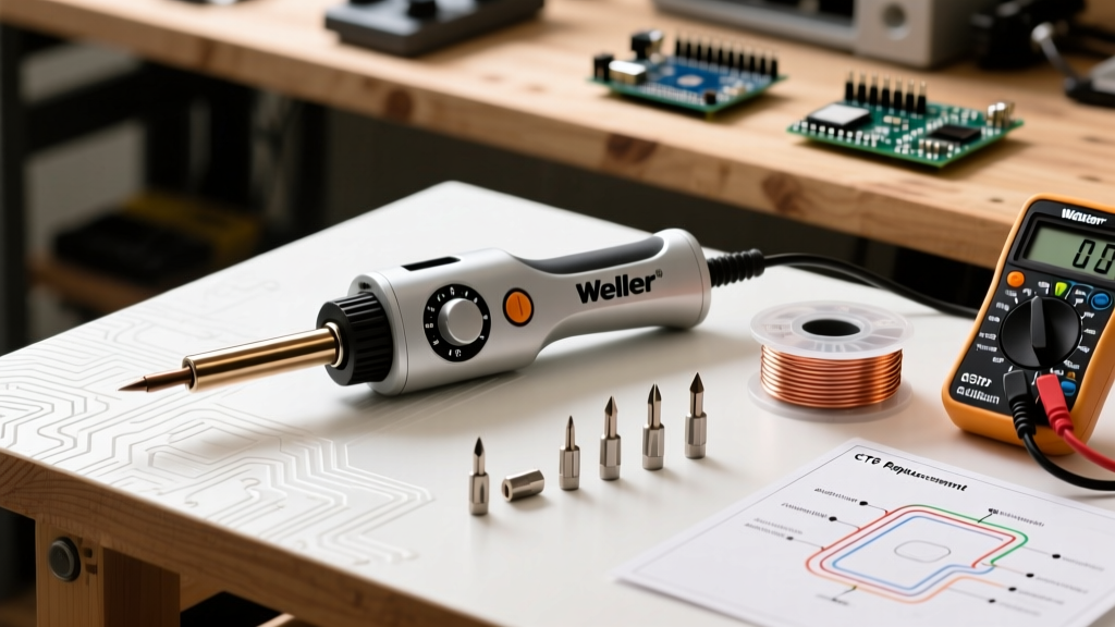
The handle is the primary interface between the operator and the tool. High-end stations prioritize low weight and thermal isolation to prevent hand fatigue during long rework sessions.
- Material Composition: Premium handles utilize ESD-safe (Electrostatic Discharge) polymers like Polyphenylene Sulfide (PPS) or high-temperature silicones. These materials withstand accidental tip contact without melting or outgassing toxic fumes.
- Weight Profiles: A standard station handle (like the Hakko FX-951) weighs approximately 52 grams without the cord. In contrast, advanced cartridge-based systems like the JBC CD-2BE push the handle weight down to roughly 40 grams by moving the heavy transformer and control logic entirely into the base station.
- Grip Geometry: The distance from the grip to the tip shoulder (the 'reach') dictates precision. A shorter reach provides better mechanical leverage for fine-pitch 0402 SMD components.
The Heating Element and Sensor Assembly
The heart of the iron is its thermal generation and feedback loop. The architecture of these parts of the soldering iron defines how quickly the tool recovers from thermal drops when touching a ground plane.
Traditional Ceramic Heaters vs. Integrated Cartridges
Older or budget-friendly irons (such as the classic Weller WES51 architecture) utilize a separate nichrome or ceramic heating element and a distinct thermocouple sensor. The tip slides over the heater, creating an air gap that acts as a thermal insulator, resulting in slower heat transfer and a 15-to-20-second recovery time on heavy joints.
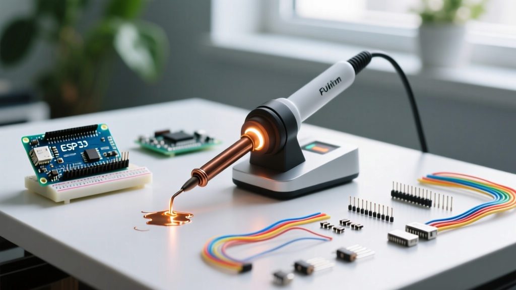
Modern professional stations utilize integrated cartridge tips. In this design, the heating element, thermocouple, and tip are a single, unified consumable unit. Because the sensor is embedded millimeters from the working face, the station detects a temperature drop and pulses high current (often via low-voltage, high-amperage induction or direct DC) to recover in under 2 seconds. While these cartridges cost between $40 and $55 each, the reduction in thermal dwell time prevents pad lifting on expensive PCBs.
Industry Standard Note: According to the IPC J-STD-001 requirements, controlling thermal dwell time is critical to prevent intermetallic compound (IMC) overgrowth, which leads to brittle, unreliable solder joints. Integrated cartridge systems are the preferred method for maintaining strict IPC compliance in high-volume environments.
Anatomy of the Soldering Tip: A Metallurgical Marvel
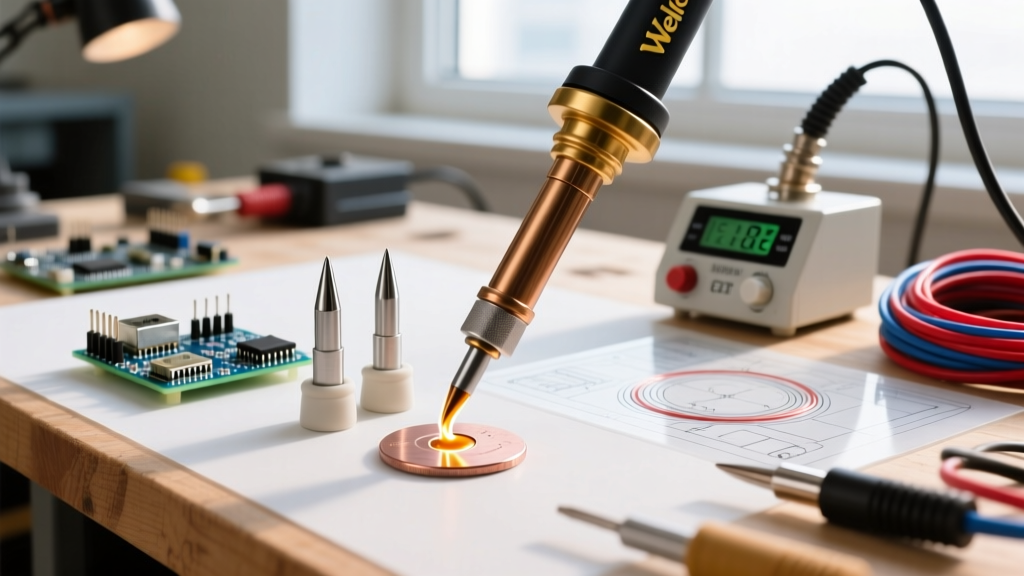
The tip is the most misunderstood of all the parts of the soldering iron. It is not a solid piece of metal; it is a complex, multi-layered composite engineered to balance thermal conductivity with chemical resistance. As detailed in resources like Adafruit's Guide to Excellent Soldering, tip maintenance is directly tied to understanding these layers.
| Layer | Material | Thickness | Primary Function |
|---|---|---|---|
| Core | Tellurium Copper (C14500) | ~85% of mass | Rapid thermal transfer from heater to joint (Conductivity: ~350 W/m·K). |
| Base Plating | Iron (Fe) | 0.1mm - 0.8mm | Protects the soft copper core from dissolving into molten solder. |
| Wetting Barrier | Chromium (Cr) or Nickel | ~0.01mm | Prevents solder from wicking up the non-working sides of the tip. |
| Working Face | Tin (Sn) Pre-tinning | Micro-layer | Prevents oxidation during storage and ensures immediate wetting upon use. |
The Iron Layer Dilemma
The iron plating layer presents a fundamental engineering trade-off. A thicker iron layer (0.8mm) drastically increases tip lifespan, making it ideal for high-temperature lead-free soldering (Sn-Ag-Cu alloys requiring 350°C+). However, iron has a much lower thermal conductivity than copper. Therefore, a thick-plated tip will exhibit a slight thermal lag compared to a thin-plated (0.1mm) tip, which is preferred for delicate, low-temperature leaded work.
Power Delivery, Cords, and Strain Relief
The umbilical cord connecting the handpiece to the station is a critical, often overlooked component.
- Silicone Jacketing: Modern high-end irons use burn-resistant silicone jackets. Unlike older PVC cords that melt and emit toxic chlorine gas when accidentally brushed by the tip, silicone withstands brief contact up to 300°C without degrading.
- Strain Relief Boots: The junction where the cord enters the handle experiences immense mechanical stress. Premium irons use Kevlar-reinforced or multi-stage molded rubber strain reliefs to prevent internal wire fatigue. A broken wire inside the strain relief is a leading cause of intermittent heating and 'Sensor Open' error codes on digital stations.
- Low-Voltage Delivery: To protect sensitive microcontrollers from Electrostatic Discharge (ESD) and leakage currents, the power delivered to the handpiece is typically stepped down to 24V AC or low-voltage DC, isolated via a transformer in the base station.
Common Failure Modes by Component
Knowing the parts of the soldering iron helps you diagnose failures accurately, saving you from replacing entire stations when a $15 part is the actual culprit.
1. Thermocouple Drift and 'Sensor Error'
If your station displays a sensor error or wildly fluctuates in temperature, the thermocouple has likely failed. In traditional irons, the thermocouple is a fragile wire wrapped near the ceramic heater. Repeated thermal cycling causes the dissimilar metals to oxidize and drift, or the wire simply snaps. Fix: Replace the heating element/sensor assembly (typically $15–$25).
2. Tip Dissolution (Coring)
If the tip develops deep pitting or a concave 'crater' on the working face, the iron plating has been breached, and the molten solder is dissolving the copper core. This is highly common when using aggressive lead-free fluxes at temperatures exceeding 400°C. Fix: Discard the tip immediately. A pitted tip cannot transfer heat evenly and will cause cold joints. Lower your working temperature to 350°C and use a tip with thicker iron plating for future work.
3. Carbonization (Blackening)
A black, crusty tip is not 'burned out'; it is suffocating. Flux residues and organic contaminants bake onto the tin layer, creating an insulating carbon shell that blocks heat transfer. As noted in SparkFun's soldering tutorials, regular cleaning is vital. Fix: Never use sandpaper or a file, as this will permanently destroy the iron plating. Instead, use a damp brass sponge and specialized tip tinner (a mixture of aggressive flux and solder powder) to chemically reduce the oxidation and re-tin the surface.
Conclusion
Mastering the parts of the soldering iron transforms you from a passive user into an informed technician. By understanding the metallurgical constraints of the tip layers, the thermal dynamics of the heating element, and the mechanical vulnerabilities of the cord assembly, you can optimize your workflow, extend the life of your consumables, and consistently produce IPC-compliant solder joints.