
Why a Dedicated Desoldering Station Outperforms Solder Wick
When tackling multi-layer printed circuit boards (PCBs) with high thermal mass, relying on copper desoldering braid is a recipe for thermal fatigue and damaged pads. A professional desoldering station integrates a thermostatically controlled heating element with a pneumatic vacuum pump, allowing you to melt and extract solder from Plated Through-Holes (PTH) in a single, fluid motion. Whether you are salvaging vintage audio equipment, replacing failed electrolytic capacitors, or reworking modern industrial controllers, mastering this tool is non-negotiable for serious electronics technicians.
According to the IPC-7711/21 standard for rework and repair, proper hole clearance is mandatory before inserting replacement components. Failure to achieve 100% barrel clearance can lead to hidden solder shorts or component lead damage during insertion. In this guide, we will break down the exact thermodynamics, tip geometries, and maintenance routines required to get surgical results from your rework equipment.
Gun-Style vs. Two-Piece Rework Architectures
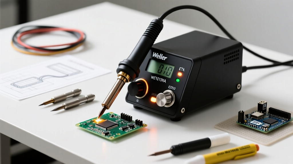
Before diving into technique, it is vital to understand your hardware architecture. The market is dominated by two primary designs. Gun-style units, like the highly popular Hakko FR-301 (retailing around $350), house the vacuum pump and heating element in a single handheld unit. They offer unparalleled portability and rapid suction response but can feel slightly front-heavy during extended sessions. Conversely, two-piece systems like the Weller WXDP 120 (approximately $650) separate the heavy pneumatic pump from the lightweight DXV80 desoldering iron. This reduces hand fatigue and is preferred for high-volume production rework, though it sacrifices bench space and requires managing an umbilical cord.
Pre-Flight Calibration: Temperature and Tip Bore Matching
The most common mistake novices make with a desoldering station is cranking the temperature to maximum to 'force' the solder out. This is a catastrophic error. Excessive heat rapidly degrades the tip plating and risks delaminating the PCB's internal copper layers. You must match the temperature to the specific alloy's liquidus point, adding only enough thermal headroom to account for the board's heat sinking.
- Leaded Solder (Sn63/Pb37): Melts at 183°C. Set your station between 350°C and 370°C.
- Lead-Free Solder (SAC305): Melts at 217°C. Set your station between 380°C and 400°C.
- High-Mass Ground Planes: Add 10°C to 15°C to your baseline, but never exceed 420°C.
Equally critical is selecting the correct tip bore size. The inner diameter of the desoldering nozzle must be slightly larger than the component lead to ensure a complete seal without touching the copper pad.
| Tip Bore Size (mm) | Ideal Lead Diameter | Common Component Types |
|---|---|---|
| 0.8mm | 0.4mm - 0.6mm | Signal diodes, small resistors, IC pins |
| 1.0mm | 0.6mm - 0.8mm | Standard 1/4W resistors, DIP ICs |
| 1.3mm | 0.8mm - 1.0mm | Electrolytic capacitors, TO-220 transistors |
| 1.6mm | 1.0mm - 1.3mm | Heavy gauge wire, large power inductors |
The 4-Step Heat-Soak and Extract Technique
Achieving a perfectly clear PTH requires a disciplined sequence. Rushing the heat-soak phase will result in a 'cold pull,' where only the surface solder is removed, leaving the barrel choked.
Step 1: Flux is Your Thermal Bridge
Never apply a desoldering station to a dry, oxidized joint. Apply a generous drop of high-quality rosin flux (such as Amtech NC-559 or Chip Quik SMD291AX) to the joint before heating. The flux breaks down surface oxides and dramatically increases the thermal transfer rate from the iron's tip to the solder mass inside the barrel. Furthermore, the flux acts as a protective barrier, preventing the extracted molten solder from oxidizing and clogging the inner PTFE tube of your desoldering gun.
Step 2: The 3-Second Dwell Rule
Place the nozzle squarely over the lead, ensuring it sits flat against the pad to create a pneumatic seal. Apply firm, downward pressure. For standard FR-4 boards, allow the iron to dwell for 2 to 3 seconds. You will visually observe the solder transition from a dull, solid state to a bright, liquid mirror finish. According to NASA Workmanship Standards (NASA-STD-8739.3), dwell times should be minimized to prevent Z-axis expansion of the PCB substrate, which is the primary mechanical cause of pad lift.
Step 3: Vacuum Trigger Timing
The moment the solder achieves a liquid state, pull the vacuum trigger. You should hear a sharp, distinct 'thwack' as the pneumatic valve opens. Hold the trigger for exactly one second to ensure the negative pressure pulls the molten solder entirely through the barrel and into the collection tube. Do not 'pump' the trigger repeatedly while the iron is on the board; this introduces cool air into the joint and causes immediate resolidification.
Step 4: Release and Visual Inspection
Release the trigger, wait a half-second for the vacuum to equalize, and then lift the iron straight up. Inspect the hole under magnification. A properly cleared PTH will allow you to see the copper plating on the inner barrel wall and the copper pad on the opposite side of the board. If solder remains, reapply flux and repeat the process. Never attempt to pry or twist the iron to break a solder joint.
Pro-Tip: If you are desoldering a multi-layer board with heavy internal ground planes, pre-heat the PCB using a hot air rework station or an infrared pre-heater to 100°C. This reduces the thermal delta, allowing your desoldering station to clear the hole in under two seconds without risking thermal shock to the vias.
Troubleshooting Common Desoldering Failures
Even with perfect technique, environmental and hardware variables can cause issues. Here is how to diagnose and resolve the most common failures:
- Pad Lift and Delamination: Cause: Dwell time exceeded 4 seconds, or the operator twisted the iron while the solder was semi-solid. Fix: Lower the temperature slightly, increase flux volume, and rely on the vacuum, not mechanical force, to clear the joint.
- Incomplete Barrel Clearance: Cause: The tip bore is too small, preventing the nozzle from seating flush against the pad, breaking the vacuum seal. Fix: Switch to a tip with a 0.3mm larger bore size.
- Solder Splatter on the PCB: Cause: The vacuum trigger was released while the tip was still in contact with the pad, blowing microscopic solder balls out of the exhaust port. Fix: Always lift the iron away from the board before releasing the trigger.
- Weak Vacuum Suction: Cause: Clogged ceramic filter, degraded O-rings, or a blockage in the PTFE tube. Fix: Perform immediate maintenance (see below).
Preventative Maintenance: Extending Pump and Element Life
A desoldering station is only as effective as its pneumatic seal. Solder vapor and flux residue will inevitably travel past the heating element and into the vacuum pathway. Neglecting maintenance will result in a burnt-out pump or a melted heating element assembly.
Cleaning the Ceramic Filter and O-Rings
After every 10 hours of active use, you must disassemble the collection tube. Inside, you will find a ceramic paper filter (such as the Hakko B5038) and a series of silicone or Viton O-rings (like the Hakko B5039). Remove the filter and tap it gently over a trash bin to dislodge solidified solder flakes. If the filter is saturated with black flux carbon, replace it immediately; a clogged filter forces the vacuum pump to work at maximum duty cycle, leading to premature motor failure.
Inspect the O-rings for flat spots or cracking. High temperatures cause silicone to degrade and lose its elasticity. Wipe the O-rings with isopropyl alcohol and apply a microscopic dab of high-temperature silicone grease to ensure an airtight seal when reassembling the tube.
Clearing the PTFE Tube and Heating Element
The white PTFE (Teflon) tube that runs through the center of the heating element is the primary pathway for molten solder. Over time, flux carbonizes inside this tube, narrowing the diameter and restricting airflow. Use the specialized twisted wire cleaning tool (often included with the station, such as the Hakko A1571) to gently ream out the tube. Insert the wire, twist clockwise, and pull out the carbon debris. Never use a metal drill bit or rigid wire, as scratching the PTFE lining will create micro-fissures where solder will permanently adhere, ruining the heating element core.
By treating your desoldering station as a precision pneumatic instrument rather than a simple soldering iron, you will achieve flawless, IPC-compliant PTH clearances, preserve the structural integrity of your PCBs, and extend the lifespan of your expensive rework equipment.