
The Science of Wire Soldering: Beyond Melting Metal
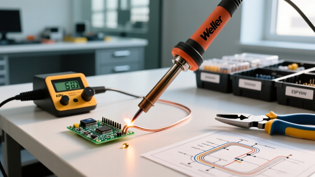
Understanding how to use a soldering iron for wires requires shifting your mindset from simply melting metal to facilitating a metallurgical bond. When soldering electrical wires, the goal is to create an intermetallic compound (IMC) layer between the copper strands and the tin-alloy solder. If your station is poorly calibrated, or if your thermal mass calculations are off, you risk creating high-resistance cold joints or damaging the wire insulation. According to the IPC-A-620 standard for cable and wire harness assemblies, a proper soldered wire connection must exhibit a smooth, bright, concave fillet with visible wire contours. This tutorial provides a professional-grade setup, calibration, and execution framework to ensure your wire splices meet aerospace and automotive reliability standards.
Essential Gear for Wire Soldering Setup
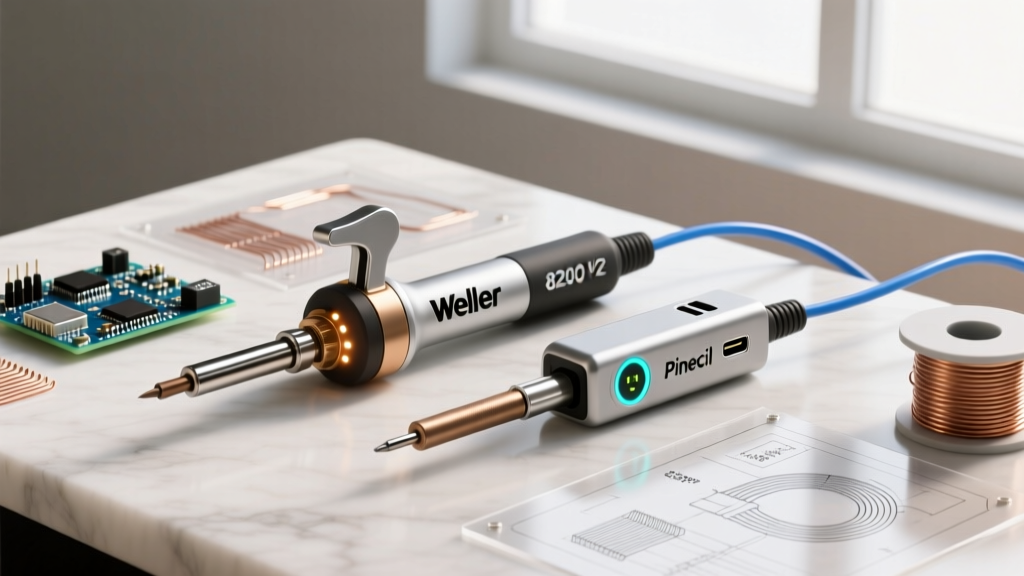
Before calibrating, you need a station capable of rapid thermal recovery. Soldering thick wires acts as a massive heat sink; if your iron cannot replenish heat quickly, the solder will freeze prematurely. Here is the recommended 2026 loadout for professional wire work:
| Equipment | Model Recommendation | Approx. Cost | Primary Use Case |
|---|---|---|---|
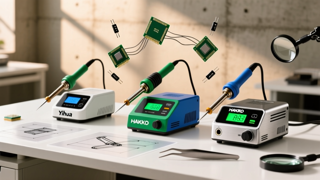
| Soldering Station | Hakko FX-888D or Weller WE1010NA | $115 - $140 | Benchtop wire splicing, high thermal recovery |
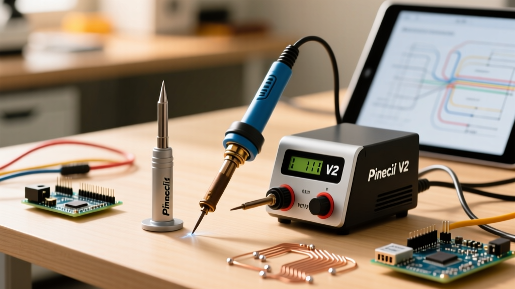
| Portable Station | Pinecil V2 (PD 65W) | $28 - $35 | Field repairs, automotive harness splicing |
| Solder Wire | Kester 245 (Sn63/Pb37) 0.031" | $35 / lb | Eutectic flow, prevents disturbed joints |
| Flux | MG Chemicals 8341 No-Clean | $18 / 10ml | Breaking down copper oxidation on stranded wires |
| Tip Thermometer | Hakko HAK-199-9 | $130 | Verifying true tip temperature vs. display |
Calibrating Your Station for Precision Wire Work
Many hobbyists blindly trust the digital readout on their soldering station. However, heating element degradation and ambient temperature shifts can cause the actual tip temperature to drift by 15°C to 30°C from the displayed value. When learning how to use a soldering iron for wires, calibration is non-negotiable.
Step-by-Step Hakko FX-888D Calibration
- Measure Baseline: Turn on the station and set it to 350°C. Let it stabilize for 3 minutes. Measure the tip using a Hakko HAK-199-9 tip thermometer. Suppose the thermometer reads 335°C.
- Enter Calibration Mode: Turn the station OFF. Hold down the UP arrow button while turning the power back ON. The display will show '00'.
- Input Password: Use the UP/DOWN arrows to enter the default password (usually '000' or '100' depending on firmware version). Press ENTER.
- Adjust Offset: The display will show the current offset. Adjust the value to compensate for the 15°C deficit. If the tip is running cold, increase the offset value.
- Verify: Exit the menu, allow the iron to re-stabilize, and remeasure. Repeat until the variance is within ±2°C.
Expert Insight: Never calibrate your station using a standard multimeter thermocouple wrapped around the tip. The thermal mass of the wire will draw heat away, yielding falsely low readings. Always use a dedicated surface-contact tip thermometer designed for soldering irons.
Temperature & Dwell Time Matrix for Common Wire Gauges
The American Wire Gauge (AWG) system dictates the thermal mass of your wire. A 24 AWG signal wire requires vastly different thermal management than a 12 AWG power wire. Use the matrix below as your baseline setup, assuming a standard Sn63/Pb37 eutectic solder alloy (melting point 183°C).
| Wire Gauge (AWG) | Recommended Tip Shape | Target Temperature | Max Dwell Time | Strip Length |
|---|---|---|---|---|
| 26 - 24 AWG | Conical (T18-B) | 320°C (608°F) | 1.0 - 1.5 seconds | 1/8" (3mm) |
| 22 - 18 AWG | Small Chisel (T18-D12) | 340°C (644°F) | 1.5 - 2.5 seconds | 3/16" (5mm) |
| 16 - 14 AWG | Medium Chisel (T18-D24) | 360°C (680°F) | 2.0 - 3.0 seconds | 1/4" (6mm) |
| 12 - 10 AWG | Large Bevel (T18-C4) | 380°C (716°F) | 3.0 - 4.0 seconds | 5/16" (8mm) |
Execution: The 5-Step Wire Tinning and Splicing Protocol
Proper technique ensures capillary action pulls the solder into the stranded wire core. As detailed in the SparkFun soldering tutorial, preparation is just as critical as the heat application.
1. Mechanical Preparation
Strip the wire to the exact lengths specified in the matrix above. For stranded wires, gently twist the strands clockwise to keep them unified. Do not twist them so tightly that you work-harden the copper, which can lead to micro-fractures under vibration.
2. Flux Application
Dip the exposed copper into no-clean paste flux or apply liquid flux with an acid brush. Flux lowers the surface tension of the molten solder and strips away microscopic copper oxide layers that form instantly when exposed to air.
3. Pre-Tinning the Wires
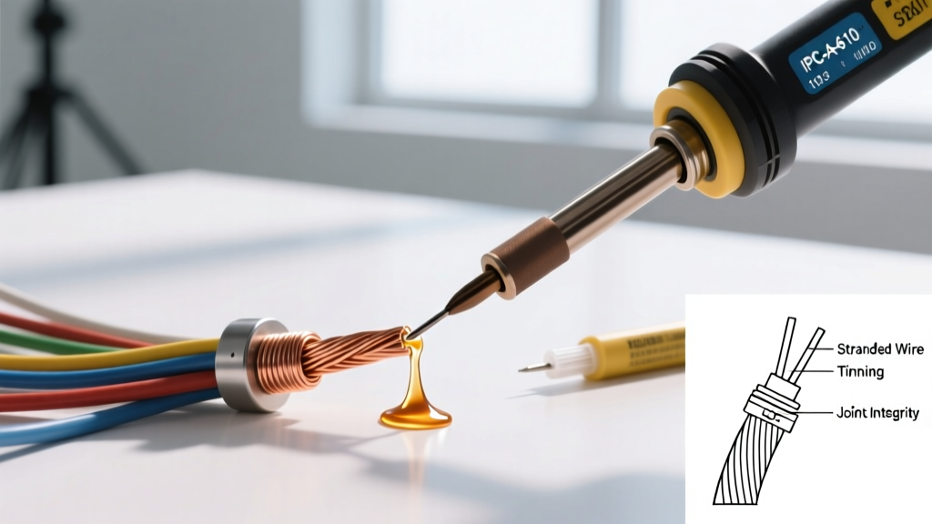
Apply a small amount of solder directly to the iron tip to create a 'heat bridge'. Touch the tip to the side of the wire (not the top), and feed solder into the opposite side of the wire. Capillary action will pull the solder through the strands. Stop when the wire looks uniformly silver.
4. The Splice (Western Union / Lineman's Splice)
Cross the two pre-tinned wires in an 'X' shape and twist them together. This provides mechanical strength before the solder even melts, ensuring the joint won't break if bumped during cooling.
5. Final Flow and Cooling
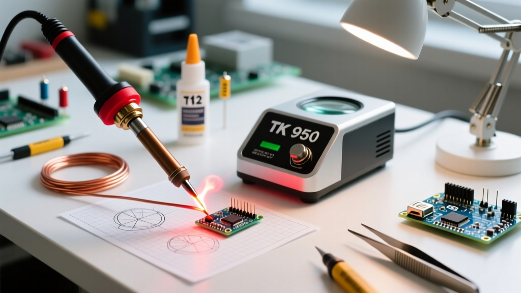
Apply the chisel tip flat against the splice. Add a tiny bit of fresh solder to the joint. The flux will boil, and the solder will flow into a smooth, concave fillet. Remove the heat and hold the wire perfectly still for 3 seconds. Moving a Sn63/Pb37 joint while it transitions from liquid to solid causes a 'disturbed joint', characterized by a dull, grainy appearance and high electrical resistance.
Troubleshooting Wire Soldering Failure Modes
Even with a calibrated Hakko FX-888D, environmental factors and material defects can cause failures. Here is how to diagnose and fix common wire soldering issues:
- The 'Grape Ball' Effect (Solder rolls off the wire): This means the wire is heavily oxidized or the tip is dead. Fix: Clean the tip in brass wool (never a wet sponge, which causes thermal shock and micro-cracks in the tip plating). Apply aggressive RA (Rosin Activated) flux to the wire and re-tin.
- Insulation Melt-Back: The heat is traveling down the copper strands and melting the PVC or silicone jacket. Fix: You are using a dwell time that is too long, or your strip length is too short. Increase your strip length to act as a thermal buffer, and use a higher temperature with a faster dwell time to minimize overall heat soak.
- Solder Wicking Under Insulation: Solder travels up the wire and under the jacket, making the flexible wire rigid and prone to snapping. Fix: You are applying too much solder or holding the iron at an upward angle. Keep the iron horizontal and use less solder. The flux will naturally stop wicking when it burns off.
- Cold Joint (Dull, lumpy appearance): Insufficient heat transfer to the core of the wire. Fix: Upgrade to a larger chisel tip to increase surface area contact. Ensure you are heating the wire, not just melting solder onto the iron tip and dropping it onto the wire.
Long-Term Tip Maintenance for Wire Work
Wire soldering is notoriously hard on soldering tips because the high thermal mass of thick copper requires higher temperatures and longer contact times, accelerating oxidation. Always keep a layer of fresh solder on the tip before turning the station off. This sacrificial layer will oxidize instead of the iron's protective chromium plating. If your tip turns black and refuses to wet, use a brass tip tinner (like Hakko 599B) to chemically strip the oxidation and re-tin the surface in one motion. By maintaining strict calibration and adhering to AWG-specific thermal profiles, your wire splices will consistently pass IPC-A-620 visual and pull-test inspections.