
Why Factory Calibration is Never Enough for SMD Work
As the electronics repair and manufacturing industries push toward ultra-fine pitch components in 2026, thermal precision is no longer optional. When configuring a soldering iron for micro-soldering tasks like 0201 metric passives or 0.35mm pitch BGA rework, a temperature deviation of just 15°C can cause catastrophic pad lift-off, tombstoning, or insufficient wetting. Factory calibration provides a baseline, but environmental variables, altitude, cartridge aging, and cold junction drift inevitably introduce thermal errors over time.
According to the IPC J-STD-001 standards for soldered electrical assemblies, maintaining strict thermal profiles is critical to preventing intermetallic compound (IMC) overgrowth, which leads to brittle solder joints. This guide provides a deep-dive, metrology-grade tutorial on calibrating modern soldering stations—specifically focusing on cartridge-based systems like the Hakko FX-951 and open-source smart irons like the Pinecil V2.
Metrology Tools Required for Precision Calibration
You cannot calibrate a precision tool with an imprecise measurement device. Relying on the station's built-in display is a circular logic fallacy; you need an independent, high-accuracy thermal measurement setup.
- K-Type Thermocouple: Use a surface-contact probe with an exposed bead (e.g., Fluke 80PK-1). Standard HVAC probes are too slow and inaccurate for micro-tips.
- High-Resolution Multimeter: A benchtop or high-end handheld DMM (like the Brymen BM869s) with a dedicated K-type thermocouple input and 0.1°C resolution.
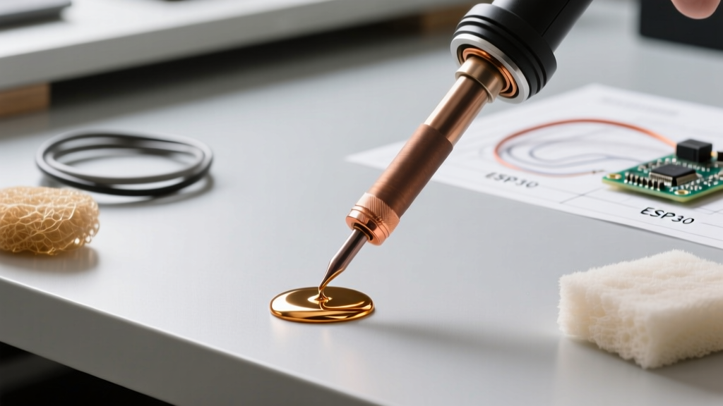
- Thermal Interface Material (TIM): A high-temperature thermal paste (e.g., Arctic Alumina) or liquid flux. This is the most skipped step by beginners. Air is a thermal insulator; applying a microscopic dab of TIM between the thermocouple bead and the soldering tip eliminates the air gap, preventing 10°C to 20°C measurement errors.
- High-Temp Silicone Mat: To provide a thermally isolated, fireproof work surface during testing.
Understanding Cold Junction Compensation (CJC)
Before adjusting tip offsets, you must understand Cold Junction Compensation. Thermocouples measure the temperature difference between the hot junction (the tip) and the cold junction (where the thermocouple wires connect to the station's internal circuitry). If the ambient temperature inside your station's handle or base unit fluctuates, the baseline shifts.
Expert Insight: Smart irons like the Pinecil V2 utilize an internal thermistor near the connector to calculate CJC. If you calibrate the iron immediately after turning it on, the internal thermistor has not yet reached thermal equilibrium with the handle, resulting in a false calibration curve as the handle warms up during use.
Step-by-Step Calibration: Hakko FX-951 (T12 Cartridge System)
The Hakko FX-951 remains a benchmark in professional labs. Its composite cartridge design houses the heater and thermocouple in a single unit, meaning calibration must be performed per-cartridge, not just per-station.
Step 1: Thermal Stabilization
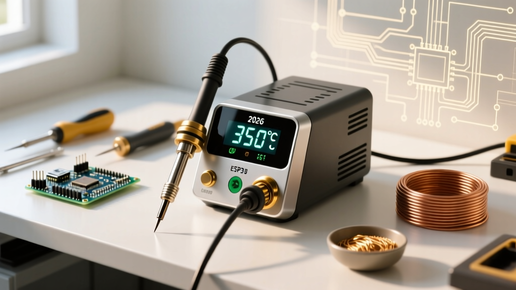
Insert a brand new or thoroughly cleaned T12-IL (micro-pencil) cartridge. Set the station to 350°C (662°F) and allow it to idle in its holder for exactly 10 minutes. This ensures the internal handle thermistor and the heating element reach a steady-state thermal equilibrium.
Step 2: Measuring Actual Tip Temperature
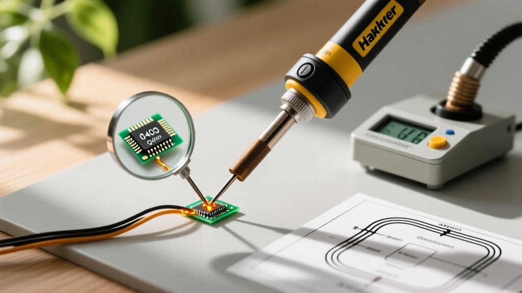
Apply a pinhead-sized drop of rosin flux or high-temp thermal paste to the very apex of the T12-IL tip. Press the K-type thermocouple bead firmly into the paste at a 45-degree angle. Wait 15 seconds for the multimeter reading to stabilize. Record this temperature (e.g., 338°C).
Step 3: Entering Calibration Mode
On the FX-951 front panel, press and hold the * (asterisk) button for approximately 3 seconds until the digital display begins to flash. The station is now in offset adjustment mode. Refer to Hakko technical support documentation if your specific firmware revision requires a passcode (default is usually 000 or unlocked on standard commercial units).
Step 4: Adjusting the Offset
Use the Up/Down arrow buttons to adjust the displayed value until it perfectly matches your multimeter's stabilized reading (338°C). Press the * button once to lock in the new offset. The station will now apply a permanent mathematical correction to that specific cartridge's thermal feedback loop.
Step-by-Step Calibration: Pinecil V2 (Smart Open-Source Iron)
The Pinecil V2 uses a RISC-V processor and allows for granular CJC calibration, which is vital when swapping between different power supplies (e.g., USB-C PD vs. DC barrel jack). As detailed in the Pinecil official wiki, proper CJC calibration ensures the iron's PID controller calculates the correct PWM duty cycle.
- Cool Down: Ensure the iron is completely at room temperature (approx. 22°C - 25°C). Do not hold it in your hand, as body heat will skew the internal thermistor. Lay it on a silicone mat.
- Enter Boot Menu: Press and hold the + button while plugging the iron into your power source. Release the button when the boot menu appears.
- Navigate to CJC: Use the + and - buttons to scroll to 'Calibration', then press + to enter. Select 'Calibrate CJC'.
- Execute: The iron will sample the internal ambient thermistor and the tip thermocouple. Because both are at room temperature, the delta should be zero. The firmware will calculate and save the offset matrix to the EEPROM.
- Verify Tip Offset: Boot normally, set to 320°C, and use the K-type thermocouple method described above. If the tip reads 315°C, navigate to the main settings menu -> 'Soldering Settings' -> 'Calibrate Tip' and apply a +5°C manual offset.
Optimized Temperature Profiles for 2026 SMD Components
Calibration allows you to trust your station's display. Once calibrated, use the following thermal matrix. These temperatures assume a calibrated tip, lead-free SAC305 solder paste, and an active flux chemistry (e.g., Amtech NC-559).
| Component Type | Target Tip Temp | Max Dwell Time | Recommended Tip Geometry |
|---|---|---|---|
| 01005 / 0201 Metric | 320°C - 330°C | 0.5s - 1.0s | Micro-Pencil (0.1mm - 0.2mm) |
| 0402 Metric Passives | 340°C | 1.0s - 1.5s | Fine Conical (0.4mm) |
| QFN-48 / QFP ICs | 350°C - 360°C | 1.5s per pin | Mini-Hoof (1.2mm - 1.5mm) |
| Ground Plane Vias | 380°C | 3.0s - 5.0s | Bevel / Chisel (2.4mm+) |
Troubleshooting Calibration Drift and Edge Cases
Symptom: The Station Reads 350°C, but the Thermocouple Reads 310°C
Failure Mode: This 40°C delta usually indicates severe oxidation on the cartridge's internal sensor sleeve or a degraded thermocouple inside the T12 cartridge. The station is pumping maximum PWM to reach the target, but the thermal transfer to the outer tip is choked by an oxide layer.
Solution: Remove the cartridge and inspect the metal contacts. Clean with isopropyl alcohol and a fiberglass scratch pen. If the delta remains above 25°C after cleaning, the internal thermocouple wire has fatigued and the cartridge must be replaced. Do not attempt to use software offsets to fix a physical thermal bottleneck; this will cause massive thermal overshoot when the iron recovers from a heat sink.
Symptom: Temperature Overshoots by 30°C Upon Initial Power-Up
Failure Mode: PID tuning mismatch. The integral (I) and derivative (D) windup values in the station's firmware are too aggressive for the thermal mass of the micro-tip installed.
Solution: On advanced stations like the JBC CD-2B or Pinecil V2, access the PID settings. Lower the 'P' (Proportional) gain slightly. Micro-tips have incredibly low thermal mass and heat up in under 2 seconds; aggressive PID curves designed for heavy chisel tips will cause them to overshoot the target before the feedback loop can react.
Frequently Asked Questions (FAQ)
How often should I calibrate my soldering iron for daily SMD repair?
For high-volume repair labs operating 8 hours a day, perform a K-type thermocouple verification weekly. You only need to adjust the offset if the drift exceeds ±5°C. For hobbyists, calibrate once every six months or whenever you switch to a new brand of soldering cartridges.
Does the type of solder alloy affect my calibration target?
Yes. Calibration ensures the tip is exactly at the temperature displayed. However, your target temperature must change based on the alloy. Lead-free SAC305 melts at 217°C–220°C and requires a tip temp of 340°C–360°C for proper wetting. Traditional Sn63/Pb37 eutectic solder melts at 183°C and only requires a tip temp of 300°C–320°C. Always calibrate to the physical reality of the tip, then adjust your setpoint to the chemical needs of the alloy.
Can I use an infrared (IR) thermal camera to calibrate my iron?
No. IR cameras measure surface emissivity. The shiny, metallic surface of a new soldering tip has incredibly low emissivity (often around 0.1 to 0.2), meaning it reflects ambient room heat rather than emitting its own. An IR camera will read a 350°C micro-tip as 150°C unless you coat the tip in high-emissivity matte black paint, which defeats the purpose of a non-destructive calibration test. Always use physical contact thermocouples with thermal paste.