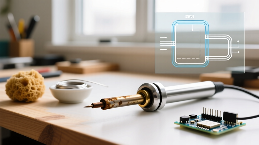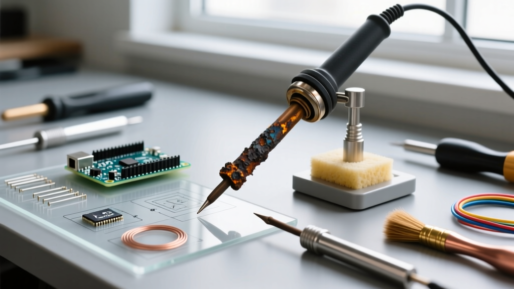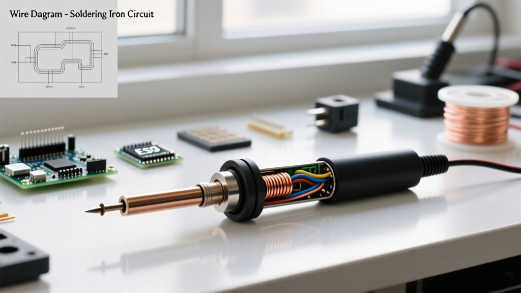

Decoding the 2 Wire Soldering Iron Architecture
When you strip back the heat-shrink tubing and examine the internal wiring of a budget-friendly soldering tool, you will likely encounter a 2 wire soldering iron configuration. Unlike advanced digital soldering stations that utilize four, five, or even six wires to manage power, sensor feedback, and grounding, a 2-wire setup relies on the absolute bare minimum: one wire for the live voltage feed and one for the neutral return (or DC+ and DC- in low-voltage DIY setups).
In 2026, while closed-loop digital stations like the Hakko FX-951 or Pinecil V2 dominate the professional workbench, the humble 2-wire iron remains ubiquitous in educational kits, quick household repairs, and remote field kits. However, using an unregulated, ungrounded 2-wire iron on modern electronics requires a deep understanding of its physical limitations, thermal lag, and the hidden electrical dangers it poses to sensitive semiconductors.
The Physics of Unregulated Nichrome Heating
The core of a standard 2-wire mains-powered iron is a resistive heating element. Typically, this consists of 24AWG or 26AWG nichrome (NiCr) wire tightly wound around a cylindrical core. In older or ultra-cheap models (priced between $5 and $12), this core is made of layered mica sheets. In slightly better models ($15 to $25), a ceramic core is used for faster heat transfer and better electrical insulation.
Because there are only two wires, there is no thermocouple or thermistor integrated into the circuit. The iron operates on a simple open-loop system. A 60W iron running on 120V AC draws exactly 0.5 Amps, relying on a fixed resistance of roughly 240 ohms. It will continuously pump 60 watts of thermal energy into the barrel until it is unplugged. The tip temperature is entirely dictated by the ambient room temperature, the thermal mass of the tip, and the heat-sinking effect of the component you are soldering.
The Hidden Dangers: Leakage Current and ESD Vulnerability
The most critical flaw of the 2 wire soldering iron is the absence of a dedicated earth ground wire connected to the metal barrel and tip. This omission creates two severe risks for electronics assembly.
1. Capacitive Coupling and AC Leakage
In a mica-core 2-wire iron, the nichrome wire is separated from the outer steel barrel by thin mica insulators and a small air gap. This physical arrangement inadvertently creates a capacitor. When 120V AC flows through the nichrome wire, capacitive coupling induces an alternating voltage on the floating metal barrel and tip.
Using a true-RMS multimeter, it is common to measure anywhere from 40V to 85V AC between the tip of a 2-wire iron and a verified earth ground. While the available current is extremely low (usually under 100 microamps, making it non-lethal to humans), this voltage is catastrophic for sensitive electronics. If you touch the tip to the gate of a MOSFET or an I/O pin on a modern microcontroller, that 60V AC spike will instantly punch through the silicon oxide layer, destroying the component.
2. Electrostatic Discharge (ESD) Accumulation
Without a path to earth ground, the tip can accumulate static charges from the environment or the user's body. According to the ESD Association Standards, modern GaN (Gallium Nitride) and SiC (Silicon Carbide) semiconductors, which are heavily used in 2026 power supply designs, can suffer latent or catastrophic damage from discharges as low as 20 volts. A floating 2-wire iron offers zero ESD protection.
Industry Standard Warning: Professional manufacturing environments strictly forbid ungrounded irons. The IPC J-STD-001 requirements for soldered electrical and electronic assemblies mandate strict ESD grounding and closed-loop temperature control to ensure joint reliability and prevent component damage.
Comparative Matrix: 2-Wire vs. Multi-Wire Soldering Systems
To understand where the 2 wire soldering iron fits in the modern ecosystem, compare its architecture against grounded and closed-loop systems.
| Feature | 2-Wire Iron (Basic Mains) | 3-Wire Iron (Grounded) | 4+ Wire Station (Closed-Loop) |
|---|---|---|---|
| Wiring | Live, Neutral | Live, Neutral, Earth Ground | Power (+/-), Sensor (+/-), Ground |
| Temperature Control | None (Fixed Wattage) | None (Fixed Wattage) | PID Closed-Loop Feedback |
| Tip Grounding | Floating (High Risk) | Hard Grounded to Earth | Hard Grounded & ESD Safe |
| Leakage Voltage | 40V - 85V AC | < 1mV AC | < 1mV AC |
| Ideal Use Case | Thick wires, plumbing, basic DIY | General chassis wiring, RC hobbies | SMD, microcontrollers, PCB repair |
| Average Cost (2026) | $8 - $18 | $25 - $45 | $110 - $250+ |
Field Modifications: Grounding a 2-Wire Iron Safely
If you are in a pinch and must use a 2 wire soldering iron on a printed circuit board, you can mitigate the leakage current and ESD risks by creating an external ground path. Note: This modification requires a verified earth ground source, such as the grounding pin of a wall outlet or a grounded metal chassis.
- Prepare the Barrel: Unplug the iron and let it cool completely. Clean the metal barrel near the base (away from the heating element) with isopropyl alcohol and light sandpaper to remove any oxidation or paint.
- Wrap the Ground Wire: Take a piece of bare 18 AWG solid copper wire. Wrap it tightly around the cleaned metal barrel 4 to 5 times. Use a small hose clamp or high-temperature Kapton tape to secure the copper wire firmly against the steel.
- Connect to Earth: Attach the other end of the copper wire to an alligator clip. Clip this directly to a verified earth ground point. Never connect this to the neutral wire of your AC mains, as neutral can carry return current and voltage drops.
- Verify with a Multimeter: Plug the iron in. Set your multimeter to AC Voltage. Measure between the soldering tip and your verified earth ground. The reading should now drop from ~60V AC down to the millivolt range.
For comprehensive safety guidelines regarding electrical grounding and preventing shock hazards in DIY environments, always refer to the OSHA Electrical Safety standards. A degraded mica insulator can cause full mains voltage to short to the barrel; an external ground wire will trip a GFCI/RCD breaker, potentially saving your life.
Thermal Recovery and Tip Selection for Unregulated Irons
Because a 2 wire soldering iron cannot increase its wattage output on demand to compensate for heat loss, thermal mass is your only tool for managing temperature drops. When soldering a large ground plane or a thick 12 AWG wire, the joint acts as a massive heat sink, rapidly pulling the tip temperature below the 220°C required to melt SAC305 lead-free solder.
The Conical Tip Trap
Most cheap 2-wire irons ship with a narrow conical (pencil) tip. This is the worst possible geometry for thermal transfer. The surface area touching the joint is minuscule, and the thermal pathway from the core to the very point of the cone is highly restricted. When you touch a conical tip to a large copper pour, the tip temperature plummets, and the user instinctively presses harder, damaging the PCB pad.
The Chisel and Hoof Solution
To maximize the efficiency of an unregulated 2-wire iron, swap the conical tip for a wide chisel or a hoof (wave) tip.
- Wide Chisel (3.2mm - 5.0mm): Maximizes surface area contact, allowing the stored thermal energy in the solid copper core of the tip to transfer rapidly into the joint.
- Hoof Tip: Excellent for drag-soldering through-hole components or scooping larger amounts of solder, utilizing the flat, concave face to hold a thermal reservoir of molten solder that acts as a liquid heat-transfer bridge.
Expert Verdict: Should You Retire Your 2-Wire Iron?
The 2 wire soldering iron is a relic of open-loop thermal design, but it is not entirely useless. It remains a highly capable tool for joining 14 AWG to 10 AWG silicone wires in RC hobbies, tinning heavy battery leads, or performing quick mechanical repairs where ESD and precise temperature control are irrelevant.
However, for any PCB-level work involving surface-mount devices (SMD), microcontrollers, or modern power semiconductors, the risks of capacitive leakage and thermal overshoot far outweigh the $100 cost of upgrading to a grounded, closed-loop station. If you must use a 2-wire iron on a PCB, always implement the external grounding modification and rely on high-thermal-mass chisel tips to prevent cold, unreliable solder joints.
Frequently Asked Questions
Can I use a 2 wire soldering iron on a car's wiring harness?
Yes. Automotive wiring repair is an ideal use case for a 2-wire iron. Since you are working with heavy-gauge copper wires and robust connectors rather than sensitive silicon, the lack of ESD grounding is not an issue. A 60W or 80W 2-wire iron provides enough sustained thermal mass to solder 16 AWG automotive wires effectively.
Why does my 2-wire iron melt the plastic handle?
This is a common failure mode in ultra-cheap 2-wire irons. Without a thermostat to cycle the power off, the barrel reaches thermal equilibrium at extremely high temperatures (often exceeding 450°C at the core). If the thermal barrier between the metal barrel and the plastic or foam handle is poorly designed, heat conducts backward, melting the handle. Always use a heat-resistant silicone sleeve or upgrade to a ceramic-core model.
Is a DC-powered 2-wire iron safer for PCBs?
A 2-wire iron powered by a low-voltage DC source (like a 24V lithium battery pack) eliminates the 120V AC capacitive leakage problem, making it much safer for CMOS chips. However, it still lacks an earth ground, meaning it offers no protection against static ESD buildup on the user's body transferring through the iron to the board.