
Decoding the Search: Why 'We Were Solders'?
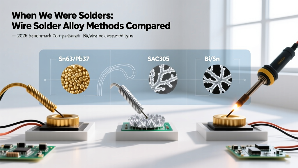
If you have ever dictated 'wire solders' into your smartphone while standing at a workbench, you have likely triggered the infamous voice-to-text glitch that searches for we were solders. While it reads like a nostalgic military memoir, this phonetic typo has become a well-known inside joke among electronics technicians and DIYers navigating the complexities of modern soldering materials. Rather than dismissing the typo, we are using it as the launching point for a comprehensive 2026 method comparison of the actual subject you meant to research: wire solder alloys and their application methods.
The landscape of wire solder has shifted dramatically. The days of universally relying on a single spool of 63/37 tin-lead are behind us. Today, a professional or advanced hobbyist must dynamically switch between eutectic leaded, silver-bearing lead-free, and low-temperature bismuth alloys depending on the thermal mass of the PCB, component sensitivity, and environmental compliance requirements. According to the IPC (Association Connecting Electronics Industries), selecting the correct alloy and matching it with the proper thermal delivery method is the primary determinant of long-term joint reliability.
The Eutectic Era: Sn63/Pb37 Method & Metallurgy
When veteran engineers joke about the past, they are often referring to the golden age of Sn63/Pb37 (63% Tin, 37% Lead). This specific ratio is eutectic, meaning it transitions directly from a solid to a liquid state at exactly 183°C (361°F) without passing through a plastic (semi-solid) phase.
Application Method
- Iron Temperature: 320°C to 350°C (608°F - 662°F).
- Dwell Time: 1.5 to 3 seconds per joint.
- Technique: Heat the pad and lead simultaneously, then feed the wire into the joint (not onto the iron tip). The rosin flux activates around 150°C, cleaning the oxidation before the alloy flows.
Because there is no plastic phase, the risk of disturbing the joint during cooling (creating a cold, grainy fracture) is virtually zero if the iron is removed cleanly. However, due to global RoHS (Restriction of Hazardous Substances) directives, Sn63/Pb37 is now strictly limited to aerospace, medical, and hobbyist applications, making it a specialty purchase rather than a default standard.
The Modern Standard: SAC305 Lead-Free Methods
For commercial electronics in 2026, SAC305 (96.5% Tin, 3.0% Silver, 0.5% Copper) is the undisputed king of lead-free wire solders. The addition of silver lowers the melting point slightly compared to pure tin and improves thermal fatigue resistance, but it fundamentally changes the soldering method.
The Thermal Challenge
SAC305 melts between 217°C and 220°C. More importantly, it possesses a higher surface tension and a distinct plastic phase. If you attempt to solder SAC305 using the exact same method as Sn63/Pb37, you will experience poor wetting, balling, and cold joints.
Expert Insight: The NASA Electronic Parts and Packaging (NEPP) Program notes that lead-free alloys require higher thermal energy transfer not just to melt, but to allow the flux chemistry sufficient time to reduce heavy copper oxidation at elevated temperatures.
Optimized SAC305 Technique
- Tip Selection: Abandon conical tips. Use a bevel (C-type) or wide chisel tip (e.g., Hakko T18-D24 or Weller RT4) to maximize surface contact area.
- Temperature Bump: Set your station to 380°C - 400°C. The higher delta-T compensates for the alloy's rapid heat dissipation into ground planes.
- Flux Synergy: SAC305 requires highly active No-Clean or Water-Soluble flux cores. Standard mild rosin will burn off before the alloy reaches its flow point.
- Dwell Time: Expect 3 to 5 seconds. You must hold the iron in place long enough for the flux to fully activate and the alloy to wick up the barrel of a plated through-hole (PTH).
The Rework Rebellion: Bismuth-Tin (Bi/Sn) Low-Temp Alloys
As PCBs become denser and components more heat-sensitive, Sn42/Bi58 (42% Tin, 58% Bismuth) has surged in popularity for step-soldering and rework. With a eutectic melting point of just 138°C (280°F), it allows technicians to solder near delicate connectors, flexible PCBs, and pre-populated SMD components without risking pad lift or thermal damage to adjacent silicon.
The method for Bi/Sn involves running your iron at a remarkably low 220°C to 250°C. The alloy flows like water, but it comes with a critical mechanical caveat: bismuth alloys are inherently brittle. They should never be used on boards subject to high mechanical shock or continuous flexing unless paired with a secondary structural support like UV-curable conformal coating or epoxy corner-bonding.
2026 Wire Solder Comparison Matrix
To help you select the correct spool for your workbench, we have compiled a direct comparison of the three dominant wire solder methods used today.
| Alloy Designation | Melting Point | Iron Temp Range | Primary Use Case | Approx. Cost (2026) |
|---|---|---|---|---|
| Sn63/Pb37 (Leaded) | 183°C (361°F) | 320°C - 350°C | Prototyping, aerospace, heavy wire lugging | $25 - $35 / lb |
| SAC305 (Lead-Free) | 217°C - 220°C | 380°C - 400°C | Commercial PCB assembly, RoHS compliance | $50 - $75 / lb* |
| Sn42/Bi58 (Low-Temp) | 138°C (280°F) | 220°C - 250°C | Step-soldering, heat-sensitive rework | $60 - $85 / lb |
*Note: SAC305 pricing fluctuates heavily based on the global spot price of silver, which has seen significant upward pressure through 2025 and 2026.
Flux Core Dynamics: The Hidden Variable
The alloy is only half the battle; the flux core inside the wire dictates the actual chemistry of the joint. Leading manufacturers like Kester and Indium Corporation formulate specific fluxes for specific alloys.
Rosin (R) vs. Rosin Mildly Activated (RMA)
Traditional Kester 44 (RMA) is the gold standard for Sn63/Pb37. It leaves a hard, amber residue that is non-corrosive but cosmetically unappealing. It requires 99% isopropyl alcohol or specialized solvents for cleanup.
No-Clean (NC) Formulations
For SAC305, No-Clean fluxes (like Kester 245) are mandatory. These fluxes contain synthetic resins that are designed to consume themselves entirely during the higher-temperature lead-free soldering process, leaving behind a microscopic, electrically inert film that does not cause dendritic growth or short circuits in high-humidity environments.
Troubleshooting Alloy-Specific Failure Modes
Even with the right wire, method errors lead to distinct visual failure modes. Here is how to diagnose your joints based on the alloy you are using:
- Grainy/Dull Joints in SAC305: Unlike leaded solder, which is naturally shiny, SAC305 joints are supposed to be slightly dull and satin-finished. However, if the joint looks cracked or heavily textured, you moved the component during the plastic phase. Increase your iron temperature by 15°C to speed up the liquid transition.
- Pad Lift with Bi/Sn: If you are using low-temp solder but still lifting pads, your iron is set too high, or you are dwelling too long, allowing heat to transfer through the pad into the FR4 substrate's epoxy resin, which degrades at 130°C (Tg).
- Tin Whiskers on Pure Tin/Leaded: Over months or years, compressive stress in the tin lattice can cause microscopic crystalline structures (whiskers) to grow, potentially shorting fine-pitch SMD leads. This is mitigated by using conformal coatings or ensuring a minimum 3% lead content in your alloy.
Final Verdict: Building a Multi-Alloy Workbench
The days of the single-spool workbench are over. To master modern electronics repair and DIY fabrication in 2026, you must adopt a multi-method approach. Keep a spool of Sn63/Pb37 for heavy-gauge wire lugging and rapid prototyping where RoHS compliance is irrelevant. Stock SAC305 with a high-activity No-Clean core for all standard commercial PCB assemblies. Finally, maintain a small syringe or half-pound spool of Sn42/Bi58 for those critical moments when you need to rework a dense BGA perimeter without melting the adjacent plastic connectors. By matching the alloy to the thermal mass and mechanical requirement of the joint, you ensure reliability that meets the highest IPC standards.