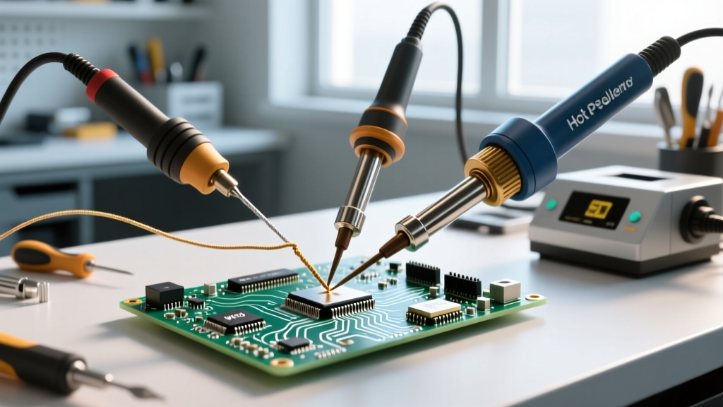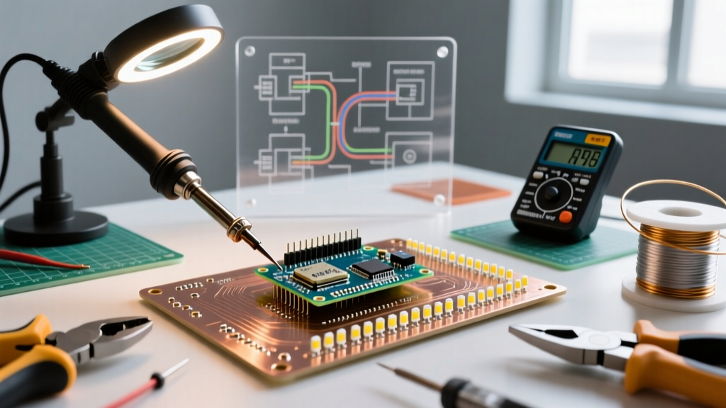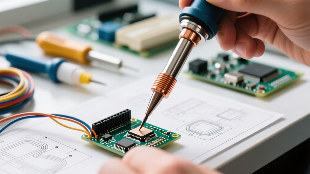

Ask a novice what a soldering bit is, and they will likely describe it as 'the hot metal point that melts the solder.' But ask an IPC-certified master instructor or a metallurgical engineer, and you will get a vastly different answer. In professional electronics manufacturing and high-reliability DIY repair, a soldering bit (or tip) is a precision-engineered thermal transfer conduit and a metallurgical bridge. It must deliver exact joules of heat to a specific thermal mass without degrading, oxidizing, or pitting.
To definitively answer what is a soldering bit from a professional standpoint, we convened a 2026 expert roundtable featuring IPC Master Instructors, production line metallurgists, and high-reliability repair technicians. Here is their comprehensive breakdown of tip anatomy, geometry, thermal dynamics, and failure modes.
The Anatomy of a Soldering Bit: A Metallurgical Breakdown
Dr. Aris Thorne, a materials scientist specializing in electronics assembly, emphasizes that a modern soldering bit is not a single piece of metal. It is a complex, multi-layered composite designed to balance thermal conductivity with chemical resistance.
'A high-quality soldering bit is an exercise in metallurgical compromise. Copper transfers heat beautifully but dissolves rapidly in molten tin. Iron resists dissolution but conducts heat poorly. The modern bit solves this through a layered architecture.' — Dr. Aris Thorne, Materials Scientist
The 4-Layer Composite Structure
- The Core (Copper): The heart of the bit is typically oxygen-free copper (OFC), chosen for its exceptional thermal conductivity (approx. 400 W/(m·K)). This core acts as a thermal capacitor, drawing heat from the ceramic heating element and storing it for transfer to the joint.
- The Plating (Iron): A layer of electroplated iron, usually between 120 to 150 microns thick, encases the working end of the copper core. According to Hakko's official tip care guidelines, this iron layer prevents the molten tin in the solder alloy from leaching the copper core, a destructive process known as 'copper erosion' or 'cratering.'
- The Barrier (Chromium/Nickel): Behind the iron plating, a micro-layer of chromium or nickel is applied. This prevents molten solder from creeping up the sides of the bit (solder creep), which can cause bridging and degrade the heating element.
- The Coating (Tin/Flux): Out of the box, the working surface is pre-tinned to prevent immediate oxidation upon first use.
Tip Geometry Matrix: Matching the Bit to the Joint
Sarah Jenkins, an IPC J-STD-001 Master Instructor, notes that understanding what a soldering bit is requires understanding its physical geometry. The shape of the bit dictates the contact area, which in turn governs the rate of thermal transfer. Using a conical tip for a heavy ground plane is a cardinal sin in soldering; it creates a high-resistance thermal bottleneck.
| Profile Geometry | Model Example (2026) | Thermal Mass & Contact | Best Application | Expert Verdict |
|---|---|---|---|---|
| Chisel (D-Series) | Hakko T18-D16 (1.6mm) | High surface area, excellent thermal transfer. | Standard through-hole, 0805/0603 SMD, wire tinning. | 'The undisputed workhorse. If you only buy one bit, make it a 1.6mm to 2.4mm chisel.' — S. Jenkins |
| Conical (B-Series) | Weller RT1 (0.1mm) | Low surface area, poor thermal recovery on large pads. | Micro-SMD (0201), fine-pitch ICs, jewelry. | 'Often misused by beginners. Only use for microscopic work where pad isolation is critical.' |
| Hoof / Bevel (C-Series) | JBC C245-945 (2.2mm) | Concave face holds a solder puddle; great for drag soldering. | SOIC/SOP drag soldering, large ground planes. | 'The bevel's concave surface acts as a solder reservoir, making drag-soldering multi-pin ICs effortless.' |
| Knife (K-Series) | Hakko T18-KR (2.3mm) | Asymmetrical edge allows pinpoint or broad contact. | QFP corners, tight clearance SMD rework. | 'The knife edge is unmatched for dragging solder into tight corners of dense microcontrollers.' |
Active vs. Passive Bits: The Thermal Recovery Revolution
Marcus Vance, a production manager for aerospace avionics, argues that the definition of a soldering bit has fundamentally shifted in the last decade due to the rise of active cartridge tips.
Passive Tips (The Traditional Standard)
In traditional stations like the legendary Hakko FX-888D or the modern Weller WE1010, the heating element and temperature sensor reside inside the handpiece wand. The bit is a passive piece of metal that slides over the ceramic heater. Thermal recovery—the time it takes for the bit to return to its set temperature after touching a cold pad—typically ranges from 6 to 12 seconds. These bits are inexpensive ($8 to $15 each) but suffer from thermal lag.
Active Cartridge Tips (The 2026 Professional Standard)
In advanced systems like the JBC CD-2BQF or the Weller WX2021, the bit and the heating element are a single, integrated cartridge. The thermocouple is located millimeters from the very tip of the working face. When the tip touches a cold copper pour, the system detects the micro-drop in temperature and dumps wattage (often up to 130W in JBC systems) into the integrated heater instantly.
'An active cartridge bit recovers its thermal equilibrium in under 2 seconds. What the bit actually 'is' in this context is a closed-loop thermal micro-reactor. It costs $45 to $55 per cartridge, but the reduction in cold solder joints and thermal pad delamination pays for itself on the first complex PCB rework.' — Marcus Vance
Expert Roundtable: Failure Modes and Edge Cases
Even the most expensive JBC or Metcal bit will be destroyed in minutes if subjected to improper handling. Our panel outlined the three most common failure modes they see in DIY and production environments.
1. Thermal Shock Cratering
Using a soaking wet cellulose sponge to clean the bit causes a rapid, violent drop in surface temperature. Dr. Thorne explains that this thermal shock causes the iron plating to micro-fracture. Once the iron cracks, molten tin penetrates the fissure, reaches the copper core, and hollows out the tip from the inside. Solution: Use dry brass wire wool (e.g., Hakko 599B) or a barely damp, high-quality cellulose sponge, wiping only when necessary.
2. High-Temperature Oxidation
Leaving a soldering station idle at 380°C (716°F) or higher causes the tin coating to oxidize into a black, crusty layer of tin oxide. This layer acts as a thermal insulator, rendering the bit useless. The IPC J-STD-001 standard strictly mandates utilizing sleep/standby modes to drop idle temperatures to 150°C-200°C. Solution: Always enable auto-sleep. Never leave a bit bare; always apply a thick glob of 63/37 rosin-core solder before placing the iron in its holster.
3. Galvanic Pitting and Flux Corrosion
Highly active water-soluble fluxes (often used in heavy-duty plumbing or specific RF applications) can chemically attack the iron plating if left on the bit after use. Furthermore, using a bit to melt acidic plumbing solder (which contains high levels of aggressive chlorides) will permanently ruin an electronics soldering bit. As outlined in the NASA Workmanship Standards for soldering, cross-contamination between plumbing fluxes and electronics assembly tools is strictly prohibited in high-reliability environments.
The Master Technician's Maintenance Protocol
To maximize the lifespan of your soldering bits, our experts recommend the following standard operating procedure (SOP) for every soldering session:
- Startup: Turn the station to 320°C (for leaded 63/37 solder) or 350°C (for lead-free SAC305). Allow 60 seconds for the core to fully saturate with heat.
- Initial Tinning: Immediately apply a liberal amount of flux-cored solder to the working face. Do not wipe it off until you are ready to make your first joint.
- During Use: Wipe the bit on brass wool only when oxidation or burnt flux residue impedes wetting. A slightly dirty tip that still wets is better than a perfectly clean, oxidized tip.
- Shutdown: Melt a large, generous blob of cheap, heavily fluxed 63/37 solder onto the tip. This 'sacrificial tinning' layer will oxidize instead of the iron plating while the tool cools. Wipe it clean only upon the next startup.
Frequently Asked Questions (FAQ)
Can I use a generic third-party replacement bit on my Hakko or Weller station?
While third-party bits (often sold in bulk for $1-$3 each) fit physically, they frequently suffer from substandard iron plating (sometimes under 50 microns) and poor copper purity. They may degrade within 10 hours of use and can damage the station's ceramic heating element due to improper dimensional tolerances. For critical work, OEM bits are strongly recommended.
Why does my brand new soldering bit turn black immediately?
If a new bit turns black and refuses to accept solder, it has flash-oxidized. This usually happens if the user turns the station temperature up to 400°C+ and leaves it idle for several minutes before applying solder. To rescue it, turn the temperature down to 250°C, apply a generous amount of specialized tip tinner/activator paste (which contains mild abrasives and fresh solder), and gently wipe with brass wool.
What is the difference between a soldering bit and a desoldering nozzle?
A soldering bit is solid, designed to transfer heat into a joint to melt solder. A desoldering nozzle is hollow and connects to a pneumatic or spring-loaded vacuum pump. Desoldering nozzles are specifically shaped to fit over component leads and suck away molten solder, requiring different thermal mass calculations and maintenance routines.