
The Anatomy of a Professional Soldering Workbench
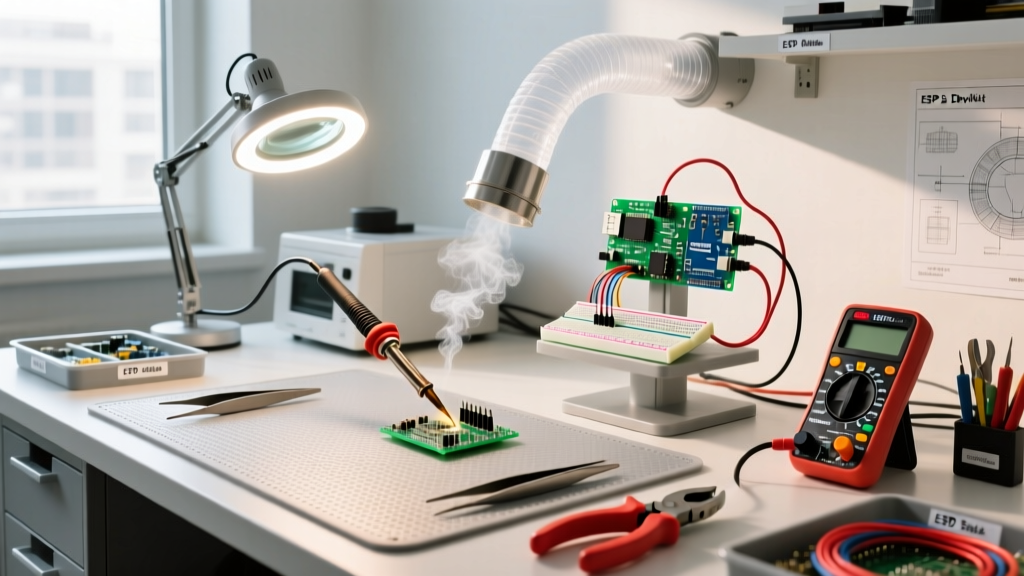
A dedicated soldering workbench is far more than just a sturdy table; it is an integrated manufacturing cell designed to optimize thermal management, electrostatic discharge (ESD) safety, and ergonomic efficiency. Whether you are reworking 0201 surface-mount components or soldering heavy-gauge XT90 connectors for drone builds, your environment dictates the quality of your joints and the longevity of your equipment. In this comprehensive guide, we break down the exact specifications, material choices, and layout strategies required to build a professional-grade electronics workbench in 2026.
Sizing and Ergonomic Dimensions
The most common mistake hobbyists make when selecting a desk for electronics work is underestimating the required depth. A standard office desk is typically 24 inches deep. However, when you place a 24-inch monitor, an oscilloscope (such as the Rigol MSO5104, which is 16.5 inches deep), and a multimeter on the surface, you are left with virtually zero clearance for your Device Under Test (DUT) and soldering iron.
The Ideal Workbench Footprint
- Depth: 30 to 36 inches minimum. This allows for a 'rear zone' for test equipment and a 'front zone' for active soldering.
- Width: 48 to 72 inches. This provides enough lateral space to separate your dirty work (flux, wire stripping, mechanical assembly) from your clean work (microscope inspection, precision soldering).
- Height: Adjustable sit-stand frames (ranging from 28 to 45 inches) are highly recommended. Precision micro-soldering requires you to lean in closely; being able to raise the bench to elbow height while standing reduces cervical spine strain significantly.
Surface Materials and ESD Compliance
Your workbench surface must protect sensitive integrated circuits from electrostatic discharge while withstanding accidental burns from a 400°C soldering tip. According to the ANSI/ESD S20.20 standard, an ESD-protected area (EPA) requires surfaces that are static dissipative, meaning they have a surface resistance between 1 x 10^6 and 1 x 10^9 ohms. This allows static charges to bleed off slowly to ground, preventing the rapid discharge that destroys silicon gates.
| Surface Material | ESD Compliance | Thermal Resistance | Best Use Case |
|---|---|---|---|
| ESD Rubber Mat (e.g., Desco 2312) | Excellent (Dissipative) | Good (Up to 300°C briefly) | Professional PCB rework and assembly |
| High-Temp Silicone Mat | Poor (Insulative) | Excellent (Up to 500°C) | Heavy-duty through-hole, wire tinning |
| Phenolic Resin Board | Moderate (Customizable) | Excellent | High-power RF and high-voltage bench |
| Bare Sealed Wood | Poor (Triboelectric risk) | Poor (Scorch risk) | Mechanical assembly only |
Crucial Grounding Note: Never ground your ESD mat directly to the building earth ground. Always use a grounding cord that contains a built-in 1-megohm safety resistor. This limits fault current to safe levels if you accidentally contact a live AC circuit while leaning on the mat.
Fume Extraction and Air Quality Management
Soldering fumes are primarily generated by the flux core, not the solder alloy itself. Rosin-based fluxes produce colophony, a known asthmagen and respiratory sensitizer. As outlined by OSHA's Hazard Communication standards, proper ventilation and Safety Data Sheet (SDS) compliance are mandatory when handling these chemicals in enclosed spaces.
Capture Velocity vs. Ambient Filtration
A common point of failure in bench setups is relying on ambient room air purifiers. To effectively capture soldering fumes, you need a localized extraction arm with a capture velocity of 100 to 150 feet per minute (fpm) at the source.
For professional setups, the BOFA AD Oracle or the Hakko FA-400 are industry standards. Ensure your filtration system uses a multi-stage filter: a pre-filter for large particulates, a HEPA filter for fine aerosols, and a deep-bed activated carbon filter to adsorb the volatile organic compounds (VOCs) released by no-clean and rosin fluxes.
Lighting and Magnification for Micro-Soldering
Inspecting cold solder joints, tombstoning, and micro-bridges on 0402 components requires precise lighting. Standard room lighting casts shadows from your hands and head, obscuring the work area.
- Illuminance: Aim for 1,000 to 1,500 lux directly at the work surface.
- Color Temperature: 5000K to 6000K (Daylight). Warm light (3000K) masks the dull, grainy texture of a cold solder joint, making it look deceptively shiny.
- CRI (Color Rendering Index): Choose LED panels or ring lights with a CRI of 95 or higher. This ensures that the subtle color differences between flux residue, bare copper, and tinned pads are accurately represented.
For magnification, an AmScope trinocular stereo zoom microscope (7X-45X) mounted on a heavy-duty boom stand is vastly superior to digital USB microscopes, which suffer from latency and poor depth perception.
Power Routing and Cable Management
A cluttered bench leads to knocked-over flux bottles and tangled probe leads. Implement an overhead gantry system using aluminum extrusions (like 80/20 Inc. T-slot framing) mounted to the rear of the desk. This allows you to drop power, compressed air, and USB data cables from above, keeping the primary work surface entirely clear. Use Panduit wiring ducts to route cables along the rear edge, and install a dedicated 20A circuit for your bench to prevent tripped breakers when running heat guns, reflow ovens, and electronic loads simultaneously.
2026 Budget Breakdown: Building Your Soldering Workbench
Building a compliant and efficient workspace requires strategic investment. Below is a realistic cost breakdown for 2026, categorized by user tier.
| Component | Hobbyist Tier | Prosumer / Repair Tier | Master Lab Tier |
|---|---|---|---|
| Workbench Frame & Top | $150 (IKEA Karlby) | $450 (Uplift V2 60x30) | $1,200 (Custom ESD Laminate) |
| ESD Mat & Grounding | $30 (Generic Amazon) | $90 (Desco Statfree T2) | $250 (Integrated ESD Top) |
| Fume Extraction | $45 (Desktop Fan/Carbon) | $250 (Hakko FA-400) | $1,800 (BOFA AD Oracle) |
| Lighting & Optics | $60 (LED Strip + Mag Glass) | $400 (AmScope Boom + Ring) | $3,500 (Leica / Vision Eng.) |
| Total Estimated Cost | $285 | $1,190 | $6,750 |
Frequently Asked Questions
Do I need an ESD mat if I only solder through-hole components?
If you are only working with passive components, relays, and basic connectors, an ESD mat is not strictly necessary. However, the moment you handle bare microcontrollers, MOSFETs, or RF modules, an ESD mat and wrist strap become mandatory to prevent latent damage that causes premature field failure.
How do I clean my ESD soldering mat without ruining it?
Never use isopropyl alcohol (IPA) or harsh solvents to clean an ESD mat, as this will strip the topical static-dissipative coating. Use a specialized ESD mat cleaner (like Desco Reztore) or a mild dish soap solution, and wipe it down with a microfiber cloth.
What is the best way to ground my soldering iron station?
According to the IPC-A-610 Acceptability of Electronic Assemblies guidelines, your soldering iron tip must be grounded to the same common point ground as your ESD mat and wrist strap. This ensures there is zero potential difference between the iron, the board, and the operator, preventing any current flow through the components during contact.