
Defining the Joint: What is Soldered in Modern Electronics?
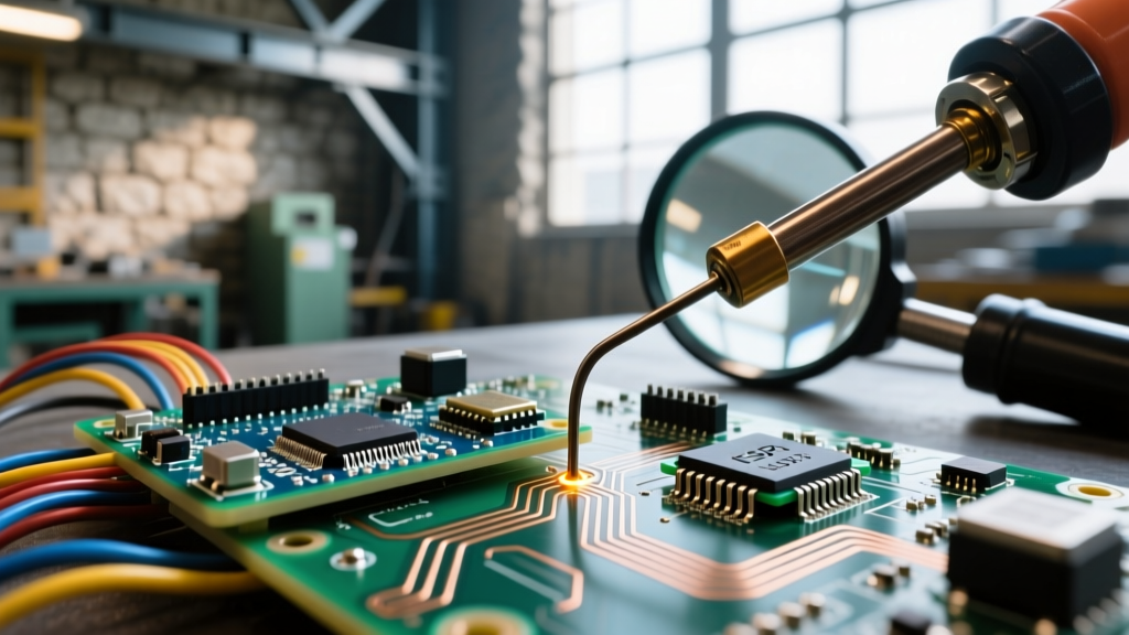
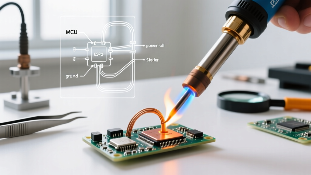
When engineers, hobbyists, and manufacturing technicians ask, "what is soldered," they are fundamentally inquiring about the metallurgical and mechanical boundaries of electrical connections. In precise terms, a soldered joint is a metallurgical bond where a filler metal (the solder) is melted above its solidus temperature to wet and fuse with base metals (like copper pads or component leads) without melting the base metals themselves. Unlike mechanical connections, what is soldered relies on the formation of an Intermetallic Compound (IMC) layer—typically Cu6Sn5 or Cu3Sn in copper-tin systems—which provides both electrical conductivity and structural integrity.
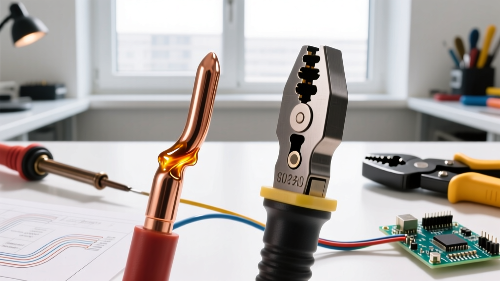
However, soldering is not the only method for terminating wires and components. In high-vibration, high-current, or automotive environments, engineers must weigh soldered connections against crimped and ultrasonic-welded alternatives. This guide breaks down the exact physics, tooling economics, and failure modes of these methods to help you decide what should be soldered, crimped, or welded in your 2026 electronic designs.
The Core Debate: Soldering vs. Crimping vs. Ultrasonic Welding
To understand what is soldered compared to other termination methods, we must evaluate the physical mechanisms that hold the joint together. Below is a comparative matrix of the three dominant electrical termination methods used in modern PCB and wire harness manufacturing.
| Method | Bonding Mechanism | Ideal Use Case | Tensile/Vibration Resistance | Relative Tooling Cost |
|---|---|---|---|---|
| Soldering | Metallurgical (IMC layer formation via heat and flux) | PCB assembly, microelectronics, static wire splices | Moderate (Brittle under high mechanical shock) | Low to Medium ($25 - $500) |
| Crimping | Mechanical deformation (Cold welding via extreme pressure) | Wire harnesses, automotive, aerospace, heavy gauge | High (Excellent vibration and pull-out resistance) | Medium to High ($50 - $10,000+) |
| Ultrasonic Welding | Solid-state friction (High-frequency acoustic vibrations) | EV battery tabs, high-current busbars, fine wire bonding | Very High (Superior thermal and mechanical stability) | Very High ($15,000 - $100,000+) |
Deep Dive: When and What is Soldered?
Soldering remains the undisputed king of Printed Circuit Board (PCB) assembly. When evaluating what is soldered on a modern logic board, we are typically looking at Surface Mount Devices (SMD) and Through-Hole Technology (THT) components. The choice of alloy dictates the thermal profile and long-term reliability of the joint.
Alloy Selection and Thermal Profiles
- SAC305 (Sn96.5/Ag3.0/Cu0.5): The industry-standard lead-free alloy. It melts between 217°C and 220°C. While compliant with RoHS directives, SAC305 requires higher reflow temperatures, which can induce thermal stress on sensitive ICs and cause pad cratering on FR-4 laminates.
- Sn63/Pb37 (Eutectic): Melting at exactly 183°C, this tin-lead alloy remains the gold standard for aerospace, medical, and hobbyist applications due to its lack of a plastic state (it transitions instantly from liquid to solid), drastically reducing the risk of cold joints caused by micro-movements during cooling.
- Sn42/Bi57/Ag1: A low-temperature lead-free alternative melting around 138°C. Gaining traction in 2026 for heat-sensitive flexible PCBs and wearable electronics, though it suffers from extreme brittleness and requires underfill for mechanical support.
Expert Insight: The phrase "what is soldered" often ignores the critical role of flux. Without a chemical flux (like Rosin Mildly Activated or No-Clean organic acids) to strip copper oxides, the molten solder will ball up and fail to wet the pad, regardless of the temperature applied. Always match your flux chemistry to your cleaning capabilities.
The Crimping Alternative: Mechanical Deformation
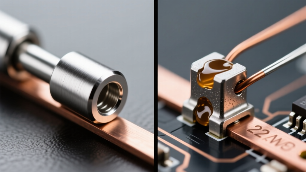
If soldering creates a metallurgical bond, crimping creates a cold weld. When a stamped metal terminal is compressed around a wire strand using a precision die, the extreme localized pressure breaks through the microscopic oxide layers on both the wire and the terminal. The metals deform and flow into one another, creating a gas-tight, electrically conductive interface without the application of heat.
Why Choose Crimping Over Soldering?
According to data from TE Connectivity's engineering guidelines, crimped connections outperform soldered wire splices in high-vibration environments (like automotive engine bays or industrial motors). Solder wicks into the wire strands via capillary action, creating a rigid boundary between the flexible wire and the stiff solder. Under continuous vibration, this rigid boundary acts as a stress concentrator, leading to copper fatigue and wire breakage. A properly crimped terminal allows the wire strands to flex right up to the bellmouth of the terminal, distributing mechanical stress evenly.
Failure Mode Analysis: Soldered vs. Crimped Joints
Understanding how joints fail is critical for reliability engineering. Here is a breakdown of the most common edge cases and failure modes for both methods.
Soldered Joint Failure Modes
- Cold Solder Joints: Caused by insufficient heat or movement during the plastic state (in non-eutectic alloys). Visually, the joint appears dull, grainy, and bulbous rather than smooth and concave.
- Tin Whiskers: Microscopic, crystalline structures of tin that grow from lead-free solder joints over time. These can bridge adjacent fine-pitch pins, causing catastrophic short circuits in satellites and medical devices.
- Thermal Fatigue Cracking: Driven by Coefficient of Thermal Expansion (CTE) mismatches between the silicon die, the solder, and the PCB. Repeated power cycling causes micro-cracks in the IMC layer, eventually leading to open circuits.
Crimped Joint Failure Modes
- Wire Strand Cutoff: If the crimp die is misaligned or the wire is inserted too far, the die can shear off outer strands, reducing the current-carrying cross-section and increasing resistance.
- Insulation Crimp Too Tight: The insulation support wings are designed to grip the wire jacket, not cut into it. Over-crimping the insulation support compromises the jacket, leading to moisture ingress and short circuits.
- Missing Bellmouth: A proper crimp must have a front and rear bellmouth (a slight flare of the terminal). Without a rear bellmouth, the sharp edge of the terminal acts like a knife on the wire strands during vibration.
Tooling and Economic Breakdown for 2026
The barrier to entry and scaling costs differ wildly between these methods. Whether you are prototyping a single IoT device or scaling a wire harness production line, your tooling budget will dictate your methodology.
Soldering Tooling Ecosystem
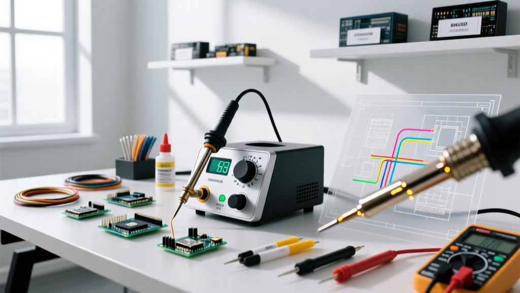
Soldering offers the lowest barrier to entry. For hobbyists and field repair technicians, the Pine64 Pinecil V2 (approx. $26) leverages USB-C PD 3.1 to deliver 65W of rapid-heat thermal power, rivaling traditional desktop stations. For professional bench work, the Hakko FX-888D (~$115) remains a reliable workhorse. However, high-volume manufacturing and advanced SMD rework require active-tip technology like the JBC CD-2BQE ($450+), which detects thermal demand and recovers heat in under two seconds.
Crimping Tooling Ecosystem
Crimping is unforgiving; the tool and the terminal must be perfectly matched. Hand tools like the Engineer PA-09 ($50) are excellent for generic JST and Dupont connectors. However, for mission-critical aerospace or automotive harnesses, manufacturers use ratcheting die sets like the TE Connectivity CERTI-CRIMP II series ($400+ per die set). These tools feature a ratchet mechanism that physically prevents the tool from opening until the exact, factory-calibrated compression force is achieved, ensuring every crimp meets IPC-J-STD-001 and UL 486A pull-force requirements.
Industry Standards Governing the Connections
When documenting what is soldered in a commercial product, you must adhere to internationally recognized workmanship standards. The NASA Electronic Parts and Packaging (NEPP) program and the IPC consortium dictate the visual and mechanical requirements for these joints.
- IPC-A-610 (Acceptability of Electronic Assemblies): The ultimate visual bible for soldered joints. It defines Class 1 (General), Class 2 (Dedicated Service), and Class 3 (High-Performance/Aerospace) requirements for solder fillet geometry, wetting angles, and cleanliness.
- IPC/WHMA-A-620: The equivalent standard specifically for cable and wire harness assemblies, detailing the exact crimp profiles, pull-test forces, and insulation spacing required for crimped terminations.
- NASA-STD-8739.3: A rigorous standard for soldered electrical connections, heavily emphasizing the use of flux control, precise heat application, and the prohibition of certain rework practices in mission-critical spaceflight hardware.
Final Verdict: Which Method Should You Choose?
Deciding what is soldered versus what is crimped comes down to the physical environment and the geometry of the connection. If you are attaching micro-components to a rigid or flexible PCB, soldering is mandatory. The precision of surface mount pads and the need for high-density routing leave no physical room for mechanical terminals.
Conversely, if you are routing power from a lithium-ion battery pack to a motor controller, or building a wiring harness for a vehicle, crimping is vastly superior. It eliminates the risk of flux-induced corrosion, avoids the thermal stress of melting wire insulation, and provides a gas-tight, vibration-proof connection that will outlast the soldered equivalent by decades in harsh environments. By matching the termination method to the mechanical and electrical demands of your specific application, you ensure long-term reliability and compliance with modern engineering standards.