
The Century-Long Quest for the Perfect Electrical Connection
When we strip a wire and slide a terminal over it today, we rarely consider the century of material science and failure analysis that made that simple action reliable. The history of soldering terminals is not just a timeline of metallurgy; it is a direct response to the catastrophic failures of early electrical systems. From the bare copper lugs of the early 1900s to the adhesive-lined, pre-soldered polyolefin connectors of 2026, the evolution of these components dictates how modern engineers, DIYers, and aerospace technicians approach wire termination.
For buyers and builders, understanding this evolution is critical. Choosing a terminal technology from the 1970s for a modern high-vibration, high-moisture environment will almost certainly result in field failure. This guide traces the historical development of soldering terminals and provides a modern buyer’s framework for selecting the right component today.
Generation 1: The Era of Bare Solder Lugs (Pre-1950s)
In the early days of radio, telegraphy, and automotive electrical systems, soldering terminals were entirely uninsulated. These were commonly known as solder lugs or solder buckets. A technician would strip the wire, twist the strands, insert them into a rolled copper or brass tube, and apply a heavy iron and rosin-core solder.
Historical Context: Early solder lugs were often tin-plated over a copper base to prevent oxidation. However, without insulation, these connections were highly susceptible to short circuits when vibration caused the bare wire strands to fan out and contact adjacent chassis grounds.
To mitigate this, technicians relied on friction tape, canvas sleeves soaked in shellac, or early liquid electrical tapes. The primary failure mode of this era was mechanical fatigue. The hard boundary between the flexible wire and the rigid soldered lug created a stress concentration point. Under continuous vibration, the copper strands would work-harden and snap just millimeters outside the solder bucket.
Generation 2: The Vinyl and Nylon Insulation Revolution (1950s–1990s)
The post-WWII boom in consumer electronics and automotive manufacturing demanded faster, safer termination methods. This era introduced the insulated terminal. Companies like AMP (now TE Connectivity) pioneered designs that integrated a polymer sleeve over the metal terminal.
The Introduction of PIDG and Vinyl Sleeves
While many of these were designed primarily for crimping, the Pre-Insulated Diamond Grip (PIDG) terminal and standard vinyl-insulated ring terminals became the standard for both crimping and soldering. The vinyl (PVC) or nylon insulation served two purposes:
- Dielectric Shielding: Preventing accidental chassis shorts.
- Strain Relief: The insulation sleeve extended over the wire jacket, distributing mechanical stress and preventing the work-hardening fatigue seen in bare lugs.
However, soldering inside vinyl-insulated terminals introduced a new set of problems. If a technician applied a 40W+ soldering iron to the metal barrel for too long, the PVC insulation would melt, shrink, or emit toxic hydrochloric gas. Furthermore, liquid flux could easily wick under the vinyl sleeve, becoming trapped and causing slow, insidious verdigris (copper corrosion) over a 5-to-10-year lifespan.
Generation 3: Heat-Shrink and Solder-Seal Terminals (2000s–Present)
The modern era of soldering terminals was defined by the marine and aerospace industries' demand for hermetically sealed connections. This led to the widespread commercialization of solder-seal heat-shrink terminals.
Unlike previous generations where the technician manually fed solder wire into the joint, modern solder-seal terminals feature pre-formed rings of solder inside a polyolefin heat-shrink tube. The inner wall is coated with a thermoplastic adhesive.
The Thermodynamics of Modern Solder Terminals
When heated with a precision heat gun (typically set between 200°C and 250°C), the sequence of events is engineered to perfection:
- The polyolefin outer shell begins to shrink at roughly 90°C.
- The inner adhesive melts and flows around the wire strands at 120°C, creating a waterproof seal.
- The pre-form solder ring melts (at 183°C for traditional Sn60/Pb40, or 217°C for modern RoHS-compliant SAC305 alloys), wicking into the wire strands via capillary action.
This completely eliminated the risk of trapped flux, as the solder is pre-fluxed, and the adhesive seals out moisture and oxygen, halting corrosion entirely.
Evolution Matrix: Comparing Terminal Generations
| Era / Generation | Insulation Type | Solder Application Method | Primary Failure Mode | 2026 Avg. Cost (per unit) |
|---|---|---|---|---|
| Pre-1950s (Bare Lugs) | None (Post-facto tape) | Manual wire feed & Iron | Strand fatigue / Shorts | $0.08 - $0.15 |
| 1960s-1990s (Vinyl/Nylon) | PVC or Nylon Sleeve | Manual wire feed & Iron | Melted insulation / Trapped flux corrosion | $0.10 - $0.25 |
| 2000s-Present (Solder-Seal) | Polyolefin + Adhesive | Pre-form ring + Heat Gun | Improper heat application / Cold shrink | $0.45 - $0.95 |
| PCB Turret Terminals | None (Board Mounted) | Manual wire wrap & Iron | Pad lifting / Thermal shock | $0.12 - $0.30 |
2026 Buyer’s Guide: Selecting the Right Soldering Terminals
Walking into an electronics supplier today presents a dizzying array of options. Here is how to select the correct soldering terminal based on modern industry standards and environmental requirements.
1. Marine, Automotive, and Heavy Machinery
Recommendation: Adhesive-Lined Solder-Seal Heat Shrink Terminals.
Why: These environments demand IP67 or higher waterproofing and extreme vibration resistance. The adhesive lining prevents the 'wicking' effect where water travels down the wire strands into the connection. Look for brands like 3M (Highland series) or Ancor Marine. Ensure the solder ring is rated for the specific wire gauge (AWG) to guarantee proper capillary fill.
2. Aerospace and High-Reliability Avionics
Recommendation: Nickel-Plated Solder Sleeves (Mil-Spec).
Why: In avionics, standard tin-plated copper can suffer from tin whiskers or galvanic corrosion when mated with specific chassis grounds. Aerospace technicians rely on transparent, flux-core solder sleeves that meet rigorous workmanship standards. According to guidelines outlined by NASA's Electronic Parts and Packaging (NEPP) program, the solder must exhibit a smooth, concave fillet with visible wire strand outlines, requiring high-transparency fluoropolymer heat-shrink sleeves for visual inspection.
3. General Electronics, Prototyping, and PCB Wiring
Recommendation: Keystone or Harwin Turret Terminals.
Why: For point-to-point wiring on printed circuit boards or phenolic panels, PCB-mount turret terminals (such as the Keystone 4000 series) remain the gold standard. These are pressed into plated through-holes and provide a robust, 360-degree mechanical anchor for the wire before soldering. They prevent the solder joint from bearing any mechanical load, adhering to the core tenet of IPC wiring standards: mechanical connections first, electrical (solder) connections second.
Common Failure Modes in Modern Soldering Terminals
Even with advanced 2026 materials, user error can defeat the best engineering. Be aware of these specific failure modes:
- The 'Cold Shrink' (Solder-Seal Terminals): If a technician uses a heat gun that is too cool, or moves away before the solder ring fully melts, the polyolefin shrinks and forms a seal, but the solder remains a solid ring. This results in a high-resistance mechanical joint disguised as a finished connection. Fix: Always wait for the solder ring to visually flow and form a fillet at the edges of the wire insulation.
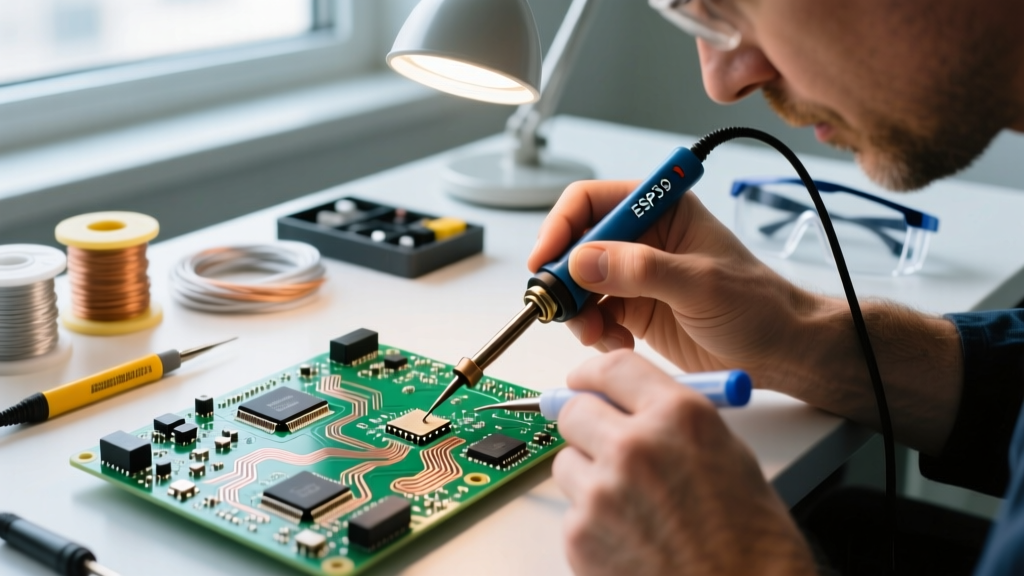
- Thermal Pad Lifting (Turret Terminals): Applying a high-wattage iron (e.g., 80W+) directly to a PCB-mounted turret terminal for more than 3 seconds can delaminate the copper pad from the FR4 fiberglass substrate. Fix: Use a temperature-controlled station set to 350°C and limit dwell time to 2.5 seconds.
- Flux Entrapment (Vinyl Terminals): Using aggressive, non-rosin liquid fluxes inside vinyl-insulated ring terminals will trap acidic residues. Over 5 years, this eats through the copper strands. Fix: If soldering vinyl terminals is unavoidable, use only mild ROL0 (Rosin, Low Activity, No Clean) flux cored solder.
Conclusion
The evolution of soldering terminals from bare, fatigue-prone copper lugs to chemically sealed, pre-soldered polyolefin systems represents a massive leap in electrical reliability. As a buyer or builder in 2026, your choice of terminal should never be based solely on upfront cost. A $0.15 vinyl terminal might save pennies today, but a $0.65 adhesive-lined solder-seal terminal guarantees decades of maintenance-free operation in harsh environments. Respect the history of these components, match the terminal generation to your environmental requirements, and your connections will stand the test of time.