
The Genesis of Electromagnetic Soldering
When most hobbyists think of soldering, they picture a simple resistive ceramic heater warming a copper tip. However, in professional aerospace, automotive, and high-reliability manufacturing sectors, the induction heating soldering system reigns supreme. By leveraging electromagnetic fields rather than direct thermal conduction, these systems offer unparalleled thermal recovery and precision. To understand why a modern RF (Radio Frequency) soldering station commands a premium price tag in 2026, we must trace its evolution from 19th-century physics experiments to the sophisticated, self-regulating workbench tools of today.
From Faraday’s Coil to the Modern Workbench
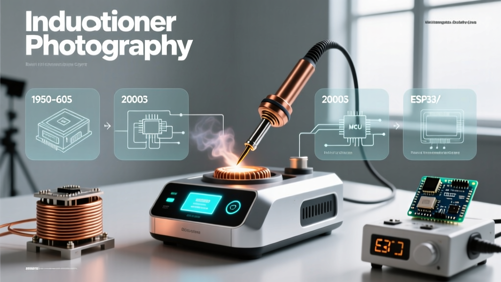
The foundational physics of induction heating dates back to 1831, when Michael Faraday discovered electromagnetic induction. For over a century, this principle was confined to heavy industry—melting steel in massive Ajax-Tama furnaces or surface-hardening automotive gears. The concept of miniaturizing a high-frequency alternating current to heat a soldering iron tip seemed impractical until the late 1970s and early 1980s.
The paradigm shift occurred when engineers at Oxytrol Systems (which would later become Metcal) realized that induction could solve the biggest flaw in traditional soldering irons: thermal lag. Early resistive irons relied on a thermocouple and a mechanical relay to cycle power on and off. This resulted in temperature overshoot, slow recovery when touching a massive ground plane, and eventual oxidation of the tip. By utilizing high-frequency eddy currents, engineers created a system that heated the tip from the inside out, directly at the working surface.
The Curie Point: The Genius of Self-Regulation
The true evolutionary leap in the induction heating soldering system was the elimination of the thermocouple. Instead of using electronic sensors to monitor temperature, modern RF stations rely on the Curie temperature—a fundamental property of ferromagnetic materials.
How Self-Regulation Works: The outer layer of an induction soldering tip is coated with a specialized nickel-iron alloy. When the RF coil generates an alternating magnetic field, eddy currents flow through this ferromagnetic layer, generating intense, localized heat. However, once the alloy reaches its specific Curie temperature (e.g., 350°C), it instantly loses its magnetic properties. The eddy currents cease, and heating stops. As soon as the tip transfers heat to a solder joint and drops below the Curie point, magnetism returns, and heating resumes in milliseconds.
This physical feedback loop is infinitely faster than any digital PID controller. According to the IPC-A-610 Acceptability of Electronic Assemblies standard, maintaining strict thermal profiles is critical for preventing cold joints and pad delamination on Class 3 aerospace boards. Induction systems achieve this natively, without user intervention.
Anatomy of a 2026 RF Soldering Tip
To appreciate the engineering, one must look at the cross-section of a modern induction tip. It is a marvel of metallurgical layering:
- Copper Core: Acts as a massive thermal reservoir, pulling heat from the outer layer and delivering it to the joint.
- Ferromagnetic Heater Layer: The nickel-iron alloy where the eddy currents are generated. The exact alloy blend dictates the tip's maximum temperature (commonly 300°C, 350°C, or 410°C).
- Iron Plating: Protects the soft copper and ferromagnetic layers from corrosive flux and molten solder erosion.
- Chromium Barrier: A microscopic layer preventing solder from wetting the non-working areas of the tip.
- Tin Wetting Layer: The pre-tinned working face for immediate thermal transfer.
Market Comparison: Induction vs. Advanced Ceramic Cartridges
While induction technology dominated the 1990s and 2000s, the 2010s saw the rise of advanced ceramic cartridge heaters (like JBC's T245 series), which integrated the heater and thermocouple directly at the tip's apex. In 2026, the market is split between high-end RF induction and advanced ceramic cartridges. Here is how the current flagship models compare:
| Feature | Metcal CV-5200 (Induction) | JBC C245 (Ceramic Cartridge) | Hakko FX-951 (Induction) |
|---|---|---|---|
| Heating Method | RF Eddy Current (SmartHeat) | Resistive Ceramic (Integrated) | RF Eddy Current |
| Thermal Recovery | Instantaneous (Physics-based) | Extremely Fast (PID-driven) | Very Fast |
| Temperature Control | Fixed by Tip Alloy (No dial) | Digital Dial (150°C - 450°C) | Fixed by Tip Alloy |
| Approx. 2026 Cost | $950 - $1,100 (Station) | $550 - $650 (Station) | $450 - $550 (Station) |
| Best Application | Heavy ground planes, IPC Class 3 | Mixed micro-SMD and heavy PTH | General production line SMD/PTH |
2026 Buyer’s Guide: Choosing Your Induction System
If you are upgrading your lab or production floor, selecting the right induction heating soldering system depends on your specific thermal demands and budget.
Tier 1: The Production Line Workhorse (Hakko FX-951)
Priced around $500, the Hakko FX-951 induction station is the entry point into RF soldering. It uses a 13.56 MHz RF generator. While it lacks the advanced digital profiling and IoT connectivity of higher-end units, its raw thermal recovery is vastly superior to standard resistive stations. It is ideal for high-volume manufacturing environments where operators do not need to adjust temperatures, reducing the risk of user error.
Tier 2: The Aerospace & R&D Standard (Metcal CV-5200)
Retailing between $950 and $1,100, the Metcal CV-5200 is the undisputed king of high-reliability rework. It features a digital interface that reads the exact tip type and remaining tip life via an RFID chip embedded in the tip sleeve. For engineers working on multi-layer PCBs with massive copper pours (e.g., 4oz to 10oz copper), the CV-5200’s ability to dump continuous wattage without overshooting the Curie limit prevents pad lifting and internal barrel cracking in vias.
Tier 3: Multi-Port & Smart Profiling Systems
For advanced BGA rework and dual-operator setups, systems like the Metcal CV-5600 ($1,500+) offer network connectivity. In 2026, these stations integrate with factory execution systems (MES), logging the exact thermal profile, tip used, and time spent on every single solder joint for complete traceability—a mandatory requirement for medical and automotive electronics.
Edge Cases, Failure Modes, and RF Interference
Despite their brilliance, induction heating soldering systems are not without specific failure modes and operational quirks that buyers must anticipate.
- RF Interference with Sensitive Analog Circuits: Because these stations broadcast high-power radio frequencies (typically 13.56 MHz or 400 kHz depending on the brand), they can induce noise in unshielded, high-impedance analog circuits on your bench. If you are probing precision audio DACs or low-level sensor amplifiers, you must power down the RF station or use heavy shielding, as the electromagnetic field will skew oscilloscope readings.
- The 'Dead Tip' Phenomenon: While the Curie point prevents thermal runaway, mechanical stress can crack the microscopic ferromagnetic layer beneath the iron plating. If a technician drops the handpiece or uses the tip as a pry tool, the internal alloy fractures. The RF field will no longer couple effectively, resulting in a 'dead tip' that fails to heat, even though the copper core is intact.
- Wrist Strap Ground Loops: Induction systems require a solid RF ground. If an operator wears a standard resistive wrist strap connected to the same bench mat as the station's ground, high-frequency skin-effect currents can sometimes cause mild tingling or interfere with the station's internal impedance matching network. Always use the manufacturer's specified ESD grounding topology.
Conclusion
The evolution of the induction heating soldering system represents a perfect marriage of quantum physics and practical workbench utility. By replacing fragile thermocouples and slow relays with the immutable laws of ferromagnetism, RF soldering stations provide a level of thermal consistency that resistive heaters simply cannot match. Whether you are assembling satellite telemetry boards or repairing heavy-duty power inverters, investing in an induction system ensures your solder joints meet the highest standards of reliability for decades to come.