
The Hidden Financial Drain of Poor Soldering Temp Management
In the electronics manufacturing and DIY repair sectors, the soldering temp is often treated as a 'set-and-forget' parameter. Operators frequently crank station dials to 400°C (752°F) to force rapid wetting, or run them too cool at 280°C (536°F) to avoid perceived component damage. However, a 2026 operational cost analysis reveals that improper temperature management is a silent profit killer. Suboptimal thermal profiles do not just yield cold joints; they accelerate consumable burnout, destroy expensive multilayer PCB pads, and inflate rework labor costs by up to 34%.
This guide breaks down the exact financial impact of soldering temp mismanagement, quantifying the cost of tip oxidation, flux exhaustion, and thermal pad delamination, while providing a data-driven framework for optimizing your thermal profiles.
Capital Expenditure: Tip Degradation and Oxidation Costs
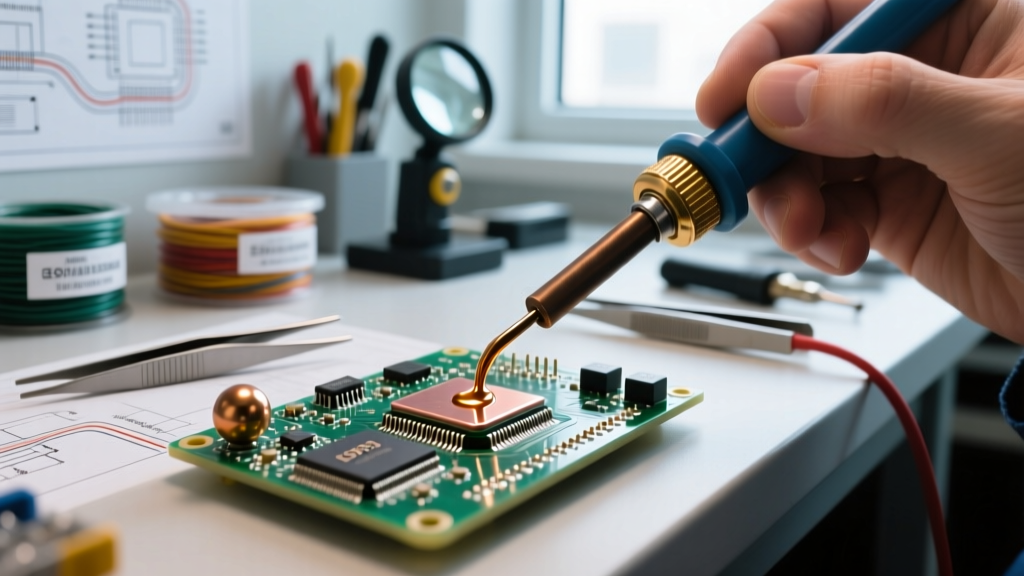
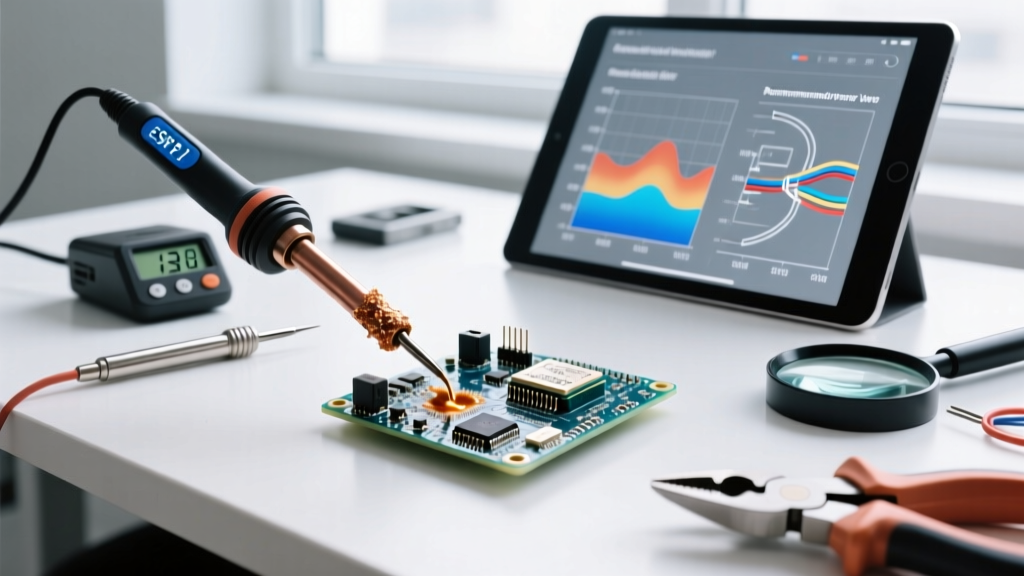
The most immediate financial casualty of an excessively high soldering temp is the soldering iron tip. Modern tips feature a copper core plated with iron to resist solder erosion, topped with a thin chromium or nickel barrier. When the idle or operating temperature exceeds 380°C (716°F), the iron plating undergoes rapid oxidation, and the flux carbonizes, creating an insulating barrier that destroys thermal transfer.
The Math Behind Tip Burnout
Consider a mid-volume production cell or a busy repair shop using standard chisel tips (e.g., Weller RT1 or Hakko T18 series).
- Average Tip Cost: $9.00 to $14.00 per unit.
- Lifespan at Optimal Temp (320°C / 608°F): ~800 to 1,200 joints before iron plating compromise.
- Lifespan at Excessive Temp (400°C / 752°F): Drops to 150 to 250 joints due to accelerated oxidation and thermal shock.
If an operator makes 500 joints a week, running the station 80°C too hot increases tip replacement frequency from once every two weeks to twice a week. Over a 50-week year, tip consumption jumps from 25 units ($250) to 100 units ($1,000) per operator. In a 10-person team, that is a $7,500 annual variance strictly from turning a dial too high.
Expert Insight: According to guidelines published by IPC J-STD-001, soldering temperatures should be optimized for the specific solder alloy and thermal mass of the joint, rather than defaulting to maximum station output. Running a station at max capacity to 'save time' violates core reliability standards and inflates consumable budgets.Material Waste: Flux Burn-Off and Solder Dross
Flux is a chemical cleaning agent designed to activate at specific thermal thresholds. For standard SAC305 (Tin/Silver/Copper) lead-free wire solder, the flux core is formulated to activate between 180°C and 220°C. If your soldering temp is set to 420°C, the flux boils and vaporizes instantly upon contact with the tip, long before it can flow to the joint and reduce surface tension.
The Rework Multiplier
When flux vaporizes prematurely, the operator is left with a dry, oxidized solder blob. To compensate, they must manually apply external liquid or tacky flux, which costs between $15 and $30 per syringe, and use 30% more solder wire to achieve a fillet.
| Cost Factor | Optimal Temp Profile (340°C) | Excessive Temp Profile (410°C) | Financial Variance (Per 10k Joints) |
|---|---|---|---|
| Wire Solder Consumption | 15 spools ($675) | 19 spools ($855) | +$180 |
| Supplemental Flux | 2 syringes ($40) | 8 syringes ($160) | +$120 |
| T Wick / Desoldering Braid | 10 spools ($50) | 25 spools ($125) | +$75 |
| Total Material Variance | $765 | $1,140 | +$375 (49% Increase) |
Thermal Damage: PCB Delamination and Component Stress
The most catastrophic costs associated with incorrect soldering temp manifest in destroyed base materials and silicon. Multilayer PCBs utilize FR-4 laminates with a Glass Transition Temperature (Tg) typically ranging from 135°C to 175°C. While the localized heat of a soldering iron dissipates, prolonged application caused by poor thermal recovery or incorrect temperature settings causes the internal copper planes to expand at different rates than the fiberglass substrate.
The Cost of Lifted Pads
When an operator uses a low soldering temp (e.g., 270°C for a heavy ground-plane through-hole joint), the iron must remain on the pad for 8 to 12 seconds to achieve wetting. This sustained thermal soak vaporizes the moisture trapped in the FR-4, leading to mezzanine cracking or pad delamination.
According to failure analysis data referenced in NASA's Workmanship Standards, lifted pads on high-density interconnect (HDI) boards often require micro-drilling and jumper wire routing to salvage, taking an experienced technician 45+ minutes. At a fully burdened labor rate of $65/hour, a single lifted pad costs $48.75 in labor, not including the scrapped $200+ PCB if the damage is irreparable.
Comparing Station Technologies: ROI on Thermal Recovery
To maintain an optimal soldering temp without resorting to excessive dial settings, the thermal recovery rate of the station is paramount. In 2026, the market is split between traditional ceramic heater stations and active RF/smart-contact stations.
Cost-Benefit Matrix: Ceramic vs. Smart RF Stations
| Station Type | Example Models (2026) | Initial CapEx | Thermal Recovery Time | Annual Tip Spend (1 Operator) |
|---|---|---|---|---|
| Standard Ceramic | Hakko FX-888D, Weller WESN51 | $110 - $160 | 8 - 14 seconds | $350 - $500 |
| Smart RF / Curie Point | Metcal MX-5200, Pace ADS200 | $650 - $950 | 1 - 2 seconds | $120 - $180 |
While a Metcal or high-end Pace station demands a $700+ premium upfront, the ability to use lower baseline temperatures (e.g., a 315°C cartridge that maintains exact temp at the joint via the Curie effect) reduces tip oxidation by up to 70%. For professional environments running 8-hour shifts, the CapEx is recovered in consumable savings and. OSHA guidelines on occupational safety also note that lower ambient tip temperatures reduce the vaporization of rosin-based fluxes into harmful colophony fumes, potentially lowering long-term HVAC filtration and health compliance costs.
Actionable Framework: Calculating Your Optimal Soldering Temp
Stop guessing your thermal profile. Implement this 3-step calibration process to minimize costs without sacrificing joint reliability:
- Establish the Baseline Alloy Melt: Identify your solder alloy. SAC305 melts at 217°C. Sn63/Pb37 melts at 183°C. Your baseline is always Melt + 40°C.
- Add Thermal Mass Offset: For standard 0805 SMD or light through-hole, add 60°C. For heavy ground-plane connectors or large capacitors, add 90°C to 110°C.
Conclusion: Temperature as a Controllable Margin
In the micro-economics of electronics assembly, the soldering temp is not merely a technical specification; it is a direct lever on your profit margins. By auditing your thermal profiles, enforcing strict idle-time auto-sleep settings, and investing in high-recovery stations, facilities can easily reclaim 15% to 20% of their annual soldering consumable budget. In 2026, where component costs and labor rates continue to climb, treating your temperature settings with the same rigor as your BOM costs is no longer optional—it is a competitive necessity.