
The Soldering Tank Decision Matrix
When outfitting an electronics lab or scaling a small-batch manufacturing line, the decision to purchase a soldering tank (commonly referred to as a dip pot or solder bath) is often treated as an afterthought. However, selecting the wrong unit leads to catastrophic failure modes: excessive dross generation, thermal lag, and in extreme cases, crucible erosion that results in molten solder spills. In 2026, with the industry firmly entrenched in lead-free assembly and high-reliability aerospace contracts, your soldering tank must be matched precisely to your metallurgical and operational requirements.
This decision framework strips away generic buying advice and focuses on the technical realities of dip soldering. Whether you are tinning magnet wire for high-frequency transformers or performing selective through-hole (TH) immersion for prototype PCBs, the following matrix will guide your capital expenditure.
Step 1: Application Profiling (Wire Tinning vs. PCB Immersion)
The physical geometry of your workload dictates the required tank topology. Soldering tanks are not universally interchangeable across tasks.
- Wire Tinning & Component Lead Prep: This requires a narrow, deep channel to minimize the exposed surface area of the molten alloy, thereby reducing oxidation (dross). Units designed for this often include specialized wire-tinning inserts or baffles. If you are following NASA-STD-8739.3 workmanship requirements for wire tinning, precise temperature control and a clean, dross-free surface are mandatory to prevent insulation scorching and ensure proper wetting.
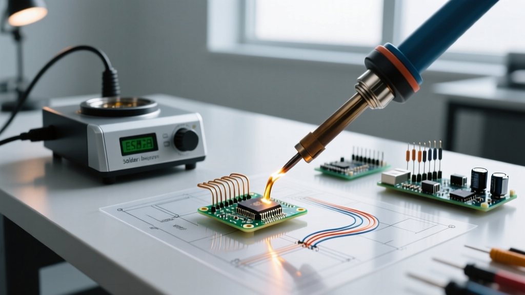
- PCB Selective Immersion & Prototyping: Dipping an entire PCB edge or performing drag-soldering requires a wide, shallow surface area. You need a tank with high thermal mass and rapid recovery times to prevent the solder from dropping below its liquidus phase when a large copper ground plane is introduced to the bath.
Step 2: The Alloy Dictates the Hardware
The most critical mistake buyers make is selecting a soldering tank based solely on capacity and wattage, ignoring the chemical interaction between the solder alloy and the crucible material.
If your facility still operates under a legacy exemption using Sn63/Pb37 (Leaded), the melting point is 183°C, and your operating temperature will hover around 245°C to 255°C. Standard cast-iron or mild-steel crucibles are perfectly adequate here and will last for years.
However, if you are processing SAC305 (Lead-Free), the metallurgy changes drastically. SAC305 has a liquidus temperature of 217°C, requiring operating temperatures between 260°C and 275°C to maintain proper wetting per IPC J-STD-001 standards. More importantly, tin-lead-free alloys are highly aggressive and will actively dissolve iron. If you use SAC305 in a standard cast-iron pot, the alloy will leach the iron from the crucible walls. Within 4 to 8 months, the pot walls will thin, develop micro-cracks, and eventually fail, spilling 300°C molten solder onto your workbench.
Critical Metallurgical Warning: For any lead-free (SAC) application, you must specify a soldering tank with a titanium crucible, a specialized ceramic-coated pot, or a high-grade stainless steel alloy designed to resist tin-iron leaching. According to data from Indium Corporation, lead-free alloys can generate up to 5 times more dross than leaded equivalents, making nitrogen-blanking capabilities a valuable feature for high-volume tanks.
2026 Soldering Tank Comparison Matrix
Below is a technical comparison of industry-standard soldering tanks categorized by their optimal use case, thermal capacity, and crucible metallurgy.
| Model / Series | Capacity / Power | Max Temp | Crucible Material | Est. Price (2026) | Best Application |
|---|---|---|---|---|---|
| Hakko FX-300 | 300g / 150W | 480°C | Ceramic Heater / Steel Pot | $240 | Light wire tinning, hobbyist TH |
| Pace ST 300 | 1kg / 200W | 450°C | Cast Iron | $480 | Leaded PCB immersion, heavy wire |
| Metcal SPX-200 | 1.2kg / 250W | 450°C | SmartHeat / Coated | $750 | Precision lead-free prototyping |
| Weller WHA3000P | 6kg / 1200W | 500°C | Titanium-Coated | $1,950 | High-volume lead-free production |
Total Cost of Ownership (TCO) and Failure Modes
The initial purchase price of a soldering tank is only a fraction of its lifecycle cost. When building your business case, factor in the following operational variables:
1. Dross Generation and Skimming Labor
Every time you skim dross (the oxidized layer of solder that forms on the surface), you are throwing away money. In a standard 3kg lead-free bath operating at 270°C in ambient air, you can expect to generate 40 to 60 grams of dross per hour. Over a standard 8-hour shift, that is nearly half a kilogram of scrapped SAC305 alloy daily. High-end tanks mitigate this via integrated nitrogen blanketing, which displaces oxygen and reduces dross formation by up to 75%.
2. Heater Degradation and Thermal Lag
Cheaper dip pots utilize mica-wound heating elements wrapped around the outside of the crucible. Over time, mica degrades, leading to uneven heat distribution and 'cold spots' in the bath. When a large PCB is dipped into a cold spot, the solder temperature drops below the liquidus phase, resulting in icicles, webbing, and cold solder joints. For critical aerospace or medical PCBs, insist on tanks with thick-cast crucibles and embedded ceramic heating elements that provide uniform thermal transfer and rapid PID-controlled recovery.
3. The True Cost of Crucible Replacement
If you mistakenly use a $400 cast-iron pot for SAC305, you will need to replace the crucible every 6 months. At $150 per replacement crucible, plus the cost of the 3kg of solder lost when the old pot is discarded, your 3-year TCO will vastly exceed the cost of a $1,500 titanium-coated industrial tank that requires zero crucible replacements over the same period.
Operational Best Practices for Dip Soldering
To maximize the lifespan of your equipment and ensure joint reliability, implement the following standard operating procedures (SOPs) on your production floor:
- Never Use a Steel Skimmer on a Coated Pot: If your tank features a titanium or ceramic non-stick coating to prevent iron leaching, using a standard steel skimming tool will scratch the coating, exposing the base metal to immediate alloy attack. Always use dedicated titanium or high-temp composite skimming tools.
- Implement a 'Pallet' System for PCBs: When dipping PCBs, do not hold them by hand with tweezers. Use high-temperature synthetic stone or titanium pallets to hold the board level. This ensures uniform immersion depth and prevents the operator's hand from acting as a heat sink or introducing contaminants to the bath.
- Flux Management: Never dip a board with wet, unactivated liquid flux directly into a deep solder tank. The rapid vaporization of flux solvents can cause micro-splatters of molten solder. Ensure flux is fully dried or pre-heated before the board touches the solder meniscus.
Final Verdict: Matching Tank to Task
If your primary workload consists of tinning 22AWG to 14AWG hookup wire for custom harnesses, a compact 150W-250W unit like the Hakko FX-300 or Metcal SPX-200 with a wire-tinning baffle is the most economical and space-efficient choice. However, if your lab is transitioning to low-volume lead-free PCB manufacturing, bypass the entry-level cast-iron models entirely. Invest in a 3kg to 6kg titanium-coated system with PID temperature stability to ensure compliance with modern reliability standards and to protect your facility from the hidden costs of alloy erosion.
FAQ: Soldering Tank Troubleshooting
Q: Why is my soldering tank taking over 45 minutes to melt the solder?
A: This is a classic symptom of a failing heating element or a degraded thermal interface between the heater and the crucible. In older mica-heater models, the mica sheets crumble over time, creating an air gap that acts as a thermal insulator. The unit must be serviced or replaced.
Q: Can I use a soldering tank for reflowing SMD components?
A: No. Soldering tanks are designed for through-hole immersion and wire tinning. Attempting to use a dip pot for SMD reflow (such as holding a PCB just above the surface to utilize the heat) will result in highly uneven heating, component tombstoning, and severe flux contamination of the solder bath.
Q: How do I safely dispose of a worn-out cast-iron solder crucible?
A: Once a crucible is deemed too thin for safe operation, allow it to cool completely. The residual solder inside must be treated as hazardous e-waste (especially if leaded). Contact a certified precious metals reclaimer or e-waste facility to process the crucible and recover the trapped solder alloy.