
The Shift to Miniaturization: Why SMD LEDs Require Precision
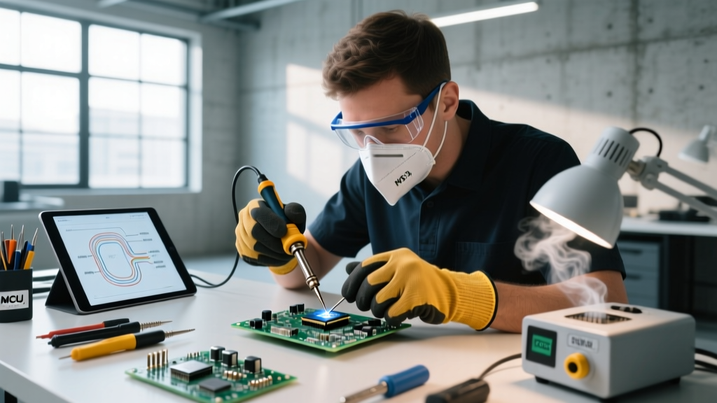
As consumer electronics, wearable tech, and custom PCB designs push toward higher densities, traditional through-hole LEDs have largely been replaced by Surface Mount Device (SMD) variants. Soldering surface mount LEDs—particularly in micro-packages like 0402 and 0201—demands a radical departure from heavy-handed iron techniques. According to the IPC-A-610 standard for electronic assembly acceptability, SMD solder joints require precise wetting and fillet formation without bridging or thermal damage to the LED's internal phosphor layers. This comprehensive guide breaks down the exact tooling, material science, and hand-soldering techniques required to master SMD LED integration in 2026.
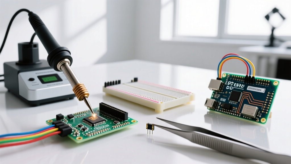
Essential Buyer Guide: Tools for SMD LED Soldering
Successfully soldering surface mount LEDs is 20% technique and 80% tooling. Attempting micro-soldering with a standard 60W chisel tip is a guaranteed path to lifted pads, melted plastic housings, and destroyed components. Here is the definitive buyer breakdown for essential SMD equipment.
Soldering Stations Comparison Matrix
| Station Model | Target Audience | Price Range (2026) | Key SMD Advantage |
|---|---|---|---|
| Hakko FX-951 | Professional / Lab | $260 - $290 | Ultra-fast thermal recovery; supports micro-pencil tips like the B2-08. |
| Pinecil V2 | Hobbyist / Portable | $26 - $35 | Open-source RISC-V controller; excellent precision for the price point. |
| Weller WE1010NA | Prosumer / Education | $105 - $125 | Stable thermal profiling; RT1 micro-tips offer great lateral visibility. |
| Quick 861DW | Advanced Rework | $240 - $270 | Dual-channel hot air and iron; essential for dense RGB LED matrices. |
Consumables: Flux and Solder Wire
For SMD LEDs, you must use ultra-fine solder wire (0.3mm to 0.5mm diameter) with a no-clean, rosin-based core. Chip Quik SMD291AX10 remains an industry favorite, offering excellent wetting at lower temperatures. Pair this with a high-tack flux syringe (like Amtech NC-559-V2-TF). Flux is absolutely non-negotiable; it reduces surface tension, preventing the dreaded tombstoning effect where the LED stands vertically on one pad.
Optical Assistance: Microscopes and Magnification
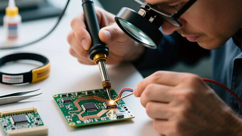
When soldering 0402 LEDs (1.0mm x 0.5mm), the naked eye is insufficient. Investing in a trinocular stereo microscope, such as the AmScope SM-4TP-B (approx. $350), is highly recommended for serious prototyping. Ensure you use a polarizing filter over your LED ring light; SMD LED epoxy lenses are highly reflective, and polarizing the light eliminates glare, allowing you to inspect the solder fillet clearly.
Understanding SMD LED Packages and Polarity
Unlike through-hole LEDs with distinct long and short legs, SMD LEDs indicate polarity via subtle visual markers on their top or bottom surfaces. Misidentifying the cathode will result in a non-functional circuit and potential thermal runaway if reverse-biased in poorly regulated driver circuits. As outlined in design guidelines by Lumileds, always verify the specific datasheet for the marking style, as they vary by manufacturer.
| Package Size | Dimensions (mm) | Common Polarity Markings | Difficulty Level |
|---|---|---|---|
| 0805 | 2.0 x 1.25 | Green dot, thick cathode line, or notched corner. | Beginner |
| 0603 | 1.6 x 0.80 | Green line on top, or internal anode shape visible. | Intermediate |
| 0402 | 1.0 x 0.50 | Faint green dot or bottom T-bar marking. | Advanced (Microscope required) |
| 0201 | 0.6 x 0.30 | Bottom metallization pattern only. | Expert (Micro-soldering) |
Step-by-Step Hand Soldering Technique
Follow this precise workflow to ensure robust, IPC-compliant joints on SMD LEDs without causing thermal shock to the semiconductor die.
- Prep and Flux: Clean the PCB pads with isopropyl alcohol (IPA). Apply a small, precise dot of tacky flux to both pads using a syringe or toothpick.
- Tin the Anchor Pad: Using a 0.4mm micro-pencil tip, apply a microscopic amount of solder to only one of the two pads. This will serve as your anchor.
- Component Placement: Grip the SMD LED with Dumont #5 titanium non-magnetic tweezers. (Titanium is crucial; magnetic steel tweezers will cause the tiny component to jump and stick to the tips). Position the LED flat over the pads, ensuring correct polarity alignment.
- Secure the Anchor: While holding the LED flat, touch your iron to the tinned anchor pad for 1-2 seconds until the solder reflows. Remove the iron, then release the tweezers once the solder solidifies (about 1 second).
- Solder the Second Pad: Bring a tiny length of 0.3mm solder wire to the opposite pad. Touch the iron to the pad and the LED terminal simultaneously. Feed the wire until a smooth, concave fillet forms. Remove wire, then iron.
- Inspect and Clean: Inspect the joint under magnification. Clean the residual flux with IPA and a soft brush to prevent long-term dendritic growth.
Troubleshooting Common SMD Defects
Tombstoning (Drawbridging)
Cause: Uneven heating of the two pads causes the solder on one side to reflow first. The surface tension of the molten solder pulls the LED upright, standing it on its end.
Fix: Apply generous fresh flux. Hold the LED flat with tweezers and reheat the lifted pad until the solder melts and the component snaps back into place. If the pad is starved of solder, add a microscopic amount of wire.
Thermal Pad Lifting and Delamination
Cause: Dwelling the iron on the pad for more than 3-5 seconds, or using excessive downward pressure, which tears the copper trace from the FR4 fiberglass substrate.
Fix: Increase the iron temperature slightly (e.g., from 320°C to 340°C) to reduce the required dwell time. According to NASA's Workmanship Standards for spaceflight hardware, dwell time on SMD pads should strictly remain under 4 seconds to prevent substrate delamination. Never press down hard; let the heat do the work.
Cracked Epoxy Lens
Cause: Touching the iron tip directly to the LED's plastic/epoxy body instead of the metal terminal, or using a dirty tip that transfers excessive, uncontrolled heat.
Fix: Keep the iron tip strictly on the PCB pad and the exposed metal terminal. If the lens is cracked, the LED's color temperature and beam angle will be permanently altered; the component must be desoldered and replaced.
Advanced Method: Solder Paste and Hot Air Reflow
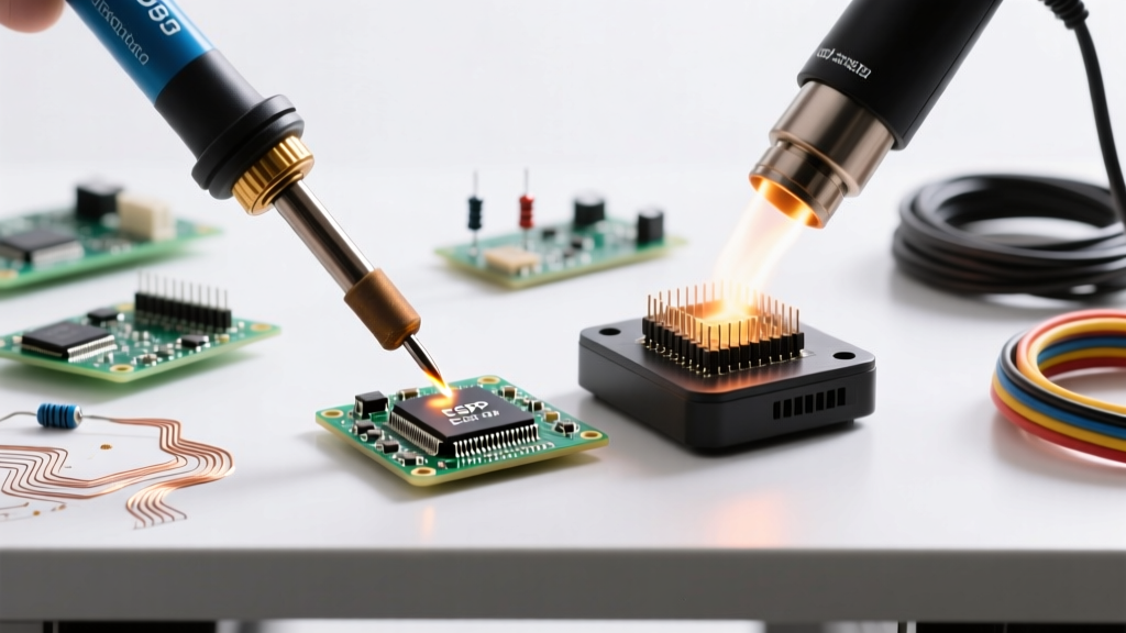
For high-volume prototyping or dense addressable LED matrices (like WS2812B or APA102 arrays), hand soldering is inefficient and risks inconsistent thermal profiles. Instead, use Type 4 or Type 5 solder paste (e.g., Chip Quik SMD4300AX) applied via a stainless steel stencil or a precision pneumatic syringe.
Place the LEDs using ESD-safe vacuum tweezers. Then, reflow using a hot air station set to 350°C with an airflow of 30%. Sweep the nozzle evenly in circular motions. Watch closely: once the paste flashes from dull grey to shiny silver, the LEDs will magically self-align due to the surface tension of the molten solder. Remove the heat immediately to prevent boiling the flux and scattering the micro-components across your workbench.
Frequently Asked Questions
Can I use lead-free solder for SMD LEDs?
Yes, but lead-free alloys (like SAC305) require higher reflow temperatures (around 240°C-250°C compared to 183°C for Sn63/Pb37). This increases the risk of thermal damage to the LED's epoxy lens and internal wire bonds. For DIY, repair, and prototyping, leaded 63/37 eutectic solder is highly recommended for its superior wetting, lower thermal stress, and sharp melting point.
How do I test an SMD LED before soldering?
Use a digital multimeter with a diode test function. Set the multimeter to diode mode, touch the red probe to the suspected anode and black to the cathode. A functioning SMD LED will emit a faint glow and show a forward voltage drop on the screen (typically 1.8V for red, 2.8V-3.3V for blue, green, and white). If it reads 'OL' (Open Loop), swap the probes. If it reads 'OL' both ways, the LED is dead.
What is the best tweezers for 0402 LEDs?
For 0402 and 0201 packages, standard steel tweezers are problematic due to magnetism and tip thickness. Invest in Dumont #5 Titanium or Brass tweezers. Titanium is non-magnetic, anti-acid, and incredibly rigid, allowing you to grip a 0.5mm component without it slipping or jumping away from the tip.