
The Termination Triad: Soldering vs. Crimping vs. Solderless
When building custom unbalanced audio interconnects, the termination method dictates the lifespan and signal integrity of the cable. In 2026, the debate among audiophiles and studio engineers centers on three primary methods: traditional RCA cable soldering, mechanical crimping, and solderless screw-terminals. While plug-and-play adapters are abundant, hard-wiring your own RCA connectors using premium bulk cable (like Mogami 2534 or Canare L-2T2S) remains the gold standard for noise rejection and impedance matching. But which termination method actually yields the best electrical and mechanical bond?
Method 1: Traditional RCA Cable Soldering (The Audiophile Standard)
Soldering creates a metallurgical bond between the copper conductor and the RCA plug's brass or tellurium-copper terminal. For audio applications, the choice of solder alloy is critical. While the EU's RoHS directives have pushed consumer electronics toward lead-free SAC305 (melting at 217°C), custom audio cable builders still heavily favor eutectic Sn63/Pb37 or near-eutectic Sn60/Pb40 alloys (melting at 183°C–188°C). The lower melting point prevents thermal degradation of the delicate PTFE or polyethylene dielectrics found in high-end coaxial audio cables.
Recommended Tools: Hakko FX-888D station set to 360°C, Kester 44 (rosin-core) or Kester 245 (no-clean) flux, and a chisel tip (e.g., Hakko T18-B) for optimal thermal transfer.
- Pros: Lowest electrical resistance, permanent gas-tight seal, allows for custom strain relief geometries.
- Cons: High skill curve, risk of thermal damage to dielectrics, requires fume extraction.
Method 2: Crimping RCA Connectors
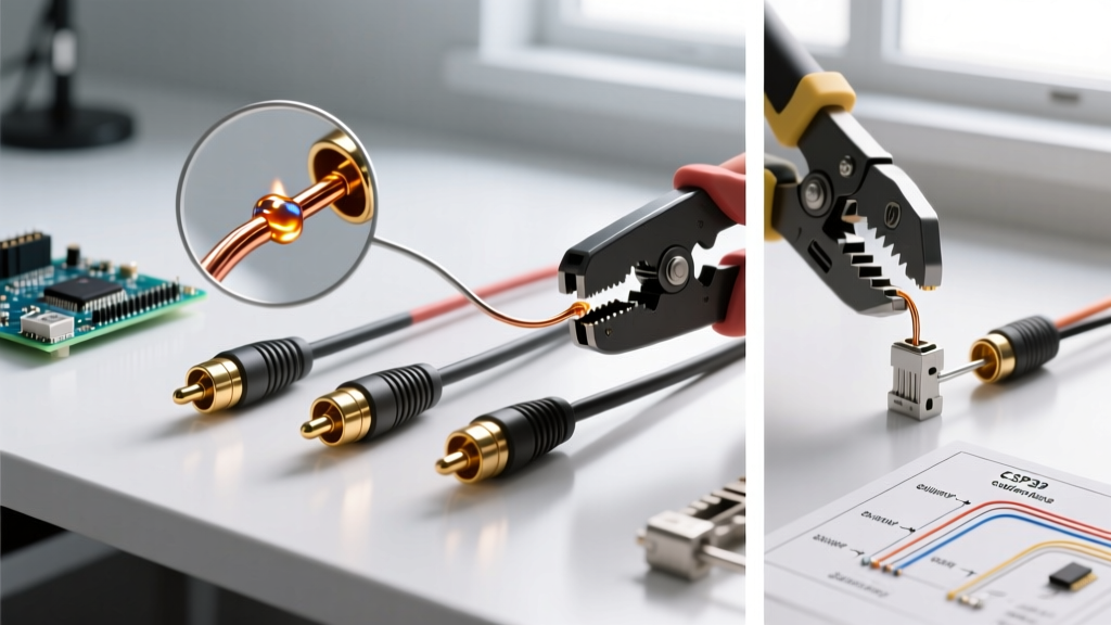
Crimping relies on extreme mechanical pressure to deform the connector barrel around the wire, creating a cold-weld gas-tight connection. This method is heavily utilized in broadcast environments where speed and consistency trump absolute minimum contact resistance. However, finding true crimp-specific RCA plugs is difficult; most standard RCA plugs feature solder cups or solder tabs. To crimp an RCA, you typically need specialized coaxial crimp connectors (like those from Belden or Trompeter) and a precision hex-crimper.
Recommended Tools: Hozan P-707 or KNIPEX 97 53 04 hex crimper, precision wire strippers.
- Pros: No heat damage to dielectrics, highly consistent in production runs, fast execution.
- Cons: Limited RCA connector compatibility, high tooling cost ($80–$150), bulkier connector profiles.
Method 3: Solderless and Screw-Terminal RCA Plugs
Solderless RCA connectors, such as the Neutrik RCA series or WBT Nextgen clones, use set-screws to clamp the center conductor and shield. These are marketed to consumers who want to build cables without a soldering iron. While adequate for temporary patching, the long-term viability is compromised by galvanic corrosion and mechanical creep (the wire relaxing under the screw pressure over time).
- Pros: Zero heat required, field-repairable, reusable.
- Cons: Highest contact resistance, prone to oxidation, screws can sever stranded wire if over-torqued.
Head-to-Head Comparison Matrix
| Feature | RCA Cable Soldering | Hex Crimping | Screw-Terminal (Solderless) |
|---|---|---|---|
| Contact Resistance | < 1 mΩ (Excellent) | < 2 mΩ (Very Good) | 5–15 mΩ (Fair to Poor) |
| Tool Investment | $60 – $120 (Iron + Extras) | $100 – $200 (Precision Crimper) | $15 – $30 (Hex Keys / Drivers) |
| Time per Connector | 3 – 5 minutes | 1 – 2 minutes | 2 – 4 minutes |
| Long-Term Reliability | 15+ years (if flux cleaned) | 20+ years (Gas-tight) | 3 – 5 years (Oxidation risk) |
| Best Use Case | Studio mastering, Hi-Fi home audio | Broadcast racks, live sound snakes | Temporary field patching, DIY beginners |
Step-by-Step Guide to Flawless RCA Cable Soldering
For the vast majority of custom audio builds, RCA cable soldering remains the undisputed champion of signal fidelity. According to the IPC J-STD-001 requirements for soldered electrical and electronic assemblies, a proper wire-to-terminal joint requires complete wetting and a smooth, concave fillet. Here is how to achieve a Class 3 equivalent joint on an RCA plug.
Phase 1: Precision Stripping and Shield Dressing
- Jacket Removal: Strip exactly 18mm of the outer PVC/TPE jacket using a calibrated wire stripper (e.g., Jokari No. 2). Do not score the braided shield underneath.
- Shield Management: Unbraid the copper shield and twist it into a single pigtail. For spiral-shielded cables, twist tightly to prevent stray strands from shorting against the center pin later.
- Dielectric Stripping: Strip 4mm of the inner dielectric to expose the center conductor. Pro Tip: Use a thermal stripper or a precision micro-stripper to avoid nicking the center conductor, which creates a stress fracture point.
Phase 2: Pre-Tinning and Sleeving
- Heat Shrink Application: Slide a 6mm piece of 2:1 polyolefin heat shrink over the cable jacket, and a 3mm piece over the twisted shield pigtail. Never forget this step before soldering.
- Tinning: Apply a microscopic amount of flux to the exposed conductors. Touch your 360°C iron to the wire and feed Sn63/Pb37 solder until it wicks into the strands. The tinned wire should look shiny and uniformly coated, not a bulbous blob.
Phase 3: The Solder Joint
- Center Pin: Insert the tinned center conductor into the RCA plug's center pin cup. Apply the iron to the outside of the cup for 1.5 seconds, then touch the solder to the wire-cup junction. Remove solder, then iron. Total heat time: under 3 seconds.
- Ground Tab: Solder the shield pigtail to the RCA's ground tab or outer barrel ring using the same technique.
- Inspection: Verify there are no solder bridges between the center pin and the ground shell. A stray strand of shield wire is the #1 cause of dead channels in DIY RCA cables.
Common Failure Modes in RCA Termination
Even experienced builders encounter issues. Understanding these failure modes is critical for passing audio signal integrity tests and ensuring longevity.
Expert Insight: "The most common cause of high-frequency roll-off in custom unbalanced cables isn't the capacitance of the cable itself, but rather the parasitic inductance introduced by poorly dressed, overly long shield pigtails inside the RCA connector hood." — Studio Wiring Best Practices, Audio Engineering Society
- Solder Wicking: If you hold the iron too long, solder wicks up under the wire insulation. This creates a stiff, brittle section right at the exit of the insulation that will eventually snap under mechanical vibration. Fix: Use a lower temperature (340°C) and limit dwell time to 2 seconds.
- Cold Joints and Rosin Inclusions: A dull, grainy joint indicates the solder cooled before crystallization was complete, or that unactivated flux is trapped inside. This increases contact resistance and introduces non-linear distortion. Fix: Ensure the iron tip is clean and tinned, and always heat the terminal, not just the solder wire.
- Dielectric Melt-Back: Using lead-free solder (SAC305) at 400°C to compensate for its poor wetting characteristics will melt the inner PTFE dielectric, causing the shield to short against the center conductor. Fix: Stick to Sn63/Pb37 for audio, or use a specialized low-temp lead-free alloy like Sn42/Bi57 (melting at 138°C) if lead is strictly prohibited in your facility.
Final Verdict: Why Soldering Wins for Audio
While crimping offers superior mechanical pull-strength for heavy-duty stage snakes, and solderless plugs offer convenience for temporary fixes, RCA cable soldering provides the optimal balance of ultra-low contact resistance, minimal parasitic capacitance, and permanent reliability for studio and audiophile environments. By investing in a temperature-controlled station, utilizing eutectic solder alloys, and adhering to strict IPC wetting standards, your custom RCA interconnects will outperform and outlast 95% of the mass-market alternatives available today.