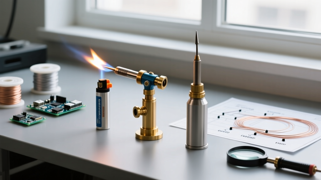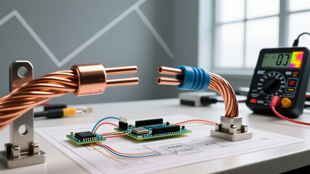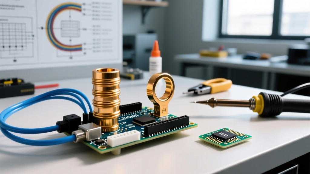

The Dual Nature of Soldering Rings in Electrical DIY
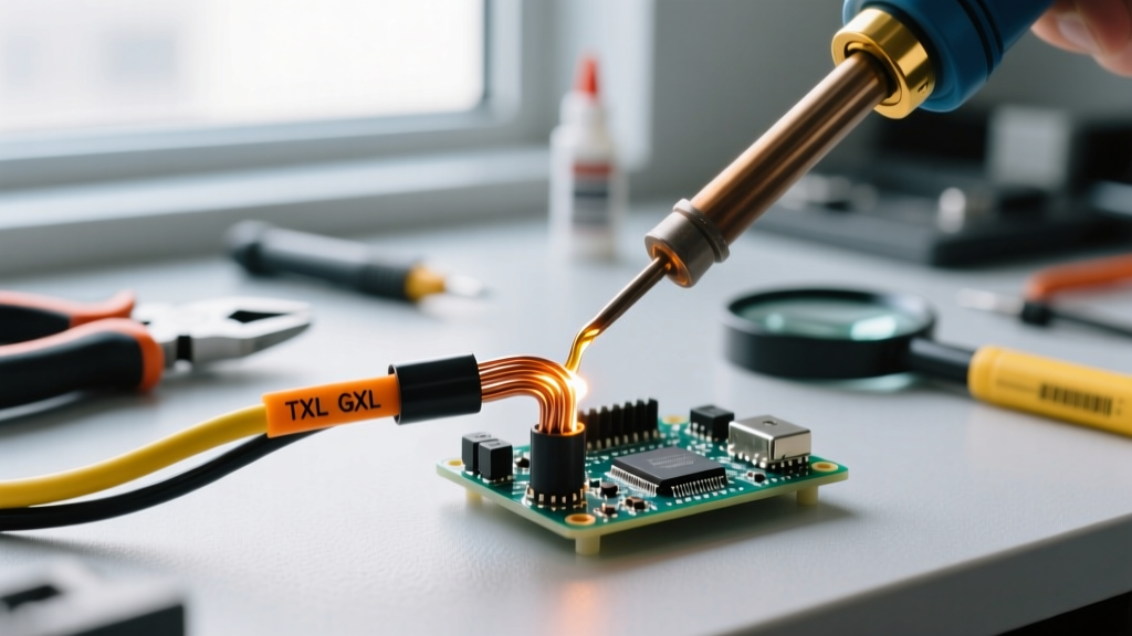
When electrical engineers and advanced DIYers discuss soldering rings together, they are typically navigating one of two distinct challenges: stacking multiple ring terminals (lugs) onto a single busbar stud, or fabricating and joining bare copper rings for custom slip rings, induction coils, and RF shielding. While both scenarios involve circular metal interfaces, the metallurgical rules, thermal requirements, and mechanical failure modes are vastly different.
This decision framework will help you determine when soldering is the optimal joining method, when it poses a catastrophic failure risk, and exactly how to execute the joint using 2026-standard equipment.
Decision Matrix 1: Stacking Ring Terminals on a Busbar
In power electronics, battery bank builds, and automotive wiring, it is common to need multiple ground or power connections on a single stud. The immediate question is whether to solder the stacked ring terminals together before bolting them down, or rely solely on mechanical compression.
The Compressive Creep Problem
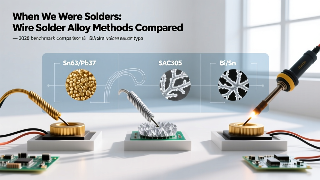
According to aerospace and aviation wiring standards, such as the FAA Advisory Circular 43.13-1B, soldering ring terminals that are subject to mechanical clamping force is strictly discouraged for high-current applications. Solder (both traditional Sn63/Pb37 and modern SAC305 lead-free alloys) is susceptible to compressive creep. When a steel or brass bolt applies torque (e.g., 15 in-lbs for a #10 screw), the solder deforms over time due to thermal cycling and continuous pressure. This leads to a loss of clamping force, increased contact resistance, and ultimately, thermal runaway.
When Soldering Stacked Terminals IS Acceptable
- Low-Current Signal Grounds: For circuits drawing under 1A where vibration is minimal, pre-tinning and lightly soldering stacked 22-18 AWG ring terminals can prevent oxidation in high-humidity environments.
- Marine Corrosion Prevention: If you must solder to seal out moisture, the solder should only seal the wire-to-barrel transition (using adhesive-lined heat shrink), not the flat mating surface of the ring itself. The ring-to-ring interface must remain bare, compressed metal.
Expert Rule of Thumb: Never use solder to fill gaps between unevenly stacked ring terminals. If your stack is uneven, use hardened steel flat washers (not zinc-plated) to distribute the bolt load evenly across the copper lugs.
Decision Matrix 2: Fabricating Custom Copper Rings (Slip Rings & Coils)
The second scenario involves physically joining bare copper rings end-to-end or layering them to build custom slip rings for robotics, or heavy-duty induction heater coils. Here, soldering is not just acceptable; it is often the only viable method for low-resistance electrical continuity without introducing the bulk of mechanical fasteners.
Alloy Selection for High Thermal Mass
Standard 60/40 rosin-core solder is insufficient for heavy copper rings due to its low shear strength and poor thermal fatigue resistance. For joining copper rings that will experience rotational friction (slip rings) or high-frequency heating (induction coils), you must upgrade your metallurgy.
- SAC305 (96.5% Sn, 3.0% Ag, 0.5% Cu): The industry standard for lead-free high-reliability joints. Melts at 217°C. Excellent for static copper ring joints.
- Sn95/Sb5 (Tin-Antimony): Melts at 235°C. Superior creep resistance, making it ideal for slip rings that will experience mechanical friction and localized heating.
- Silver-Bearing Solder (e.g., Kester #245): Contains 2% silver, which prevents the solder from leaching silver platings off specialized slip ring brushes.
Thermal Mass & Equipment Selection Matrix
Copper is an aggressive heat sink. When soldering rings together, a standard 40W hobby iron will result in a cold joint because the copper ring dissipates the heat faster than the iron can replenish it. You must match your station's thermal recovery rate to the ring's cross-sectional area.
| Ring Material & Size | Cross-Section | Minimum Iron Wattage | Recommended Tip Geometry | Flux Requirement |
|---|---|---|---|---|
| 20-16 AWG Copper Wire Rings | 0.5 - 1.3 mm² | 45W - 65W (e.g., Pinecil V2) | Conical or Narrow Chisel (1.6mm) | No-Clean Rosin (e.g., Kester 186) |
| 12-8 AWG Busbar / Lug Rings | 3.3 - 8.3 mm² | 70W - 90W (e.g., Hakko FX-951) | Wide Chisel or Bevel (3.2mm+) | Tacky Flux (e.g., Amtech TAC-5200) |
| 1/4" Copper Tubing / Heavy Coil | 15+ mm² | 150W+ or Micro-Torch | Massive Chisel (5mm+) or Induction | High-Activity Paste (e.g., Harris Stay-Clean) |
For a comprehensive look at acceptable solder joint criteria and thermal profiling, refer to the IPC-A-610 standard documentation, which outlines the exact wetting angles and fillet requirements for heavy thermal mass connections.
Step-by-Step Execution Protocol for Heavy Copper Rings
If your decision framework dictates that soldering the copper rings together is the correct path, follow this exact sequence to avoid thermal shock and flux entrapment.
- Mechanical Preparation: Abrade the mating surfaces of the copper rings with 400-grit sandpaper or a fiberglass scratch pen until bright copper is visible. Do not touch the metal with bare skin afterward.
- Flux Application: Apply a generous amount of high-activity paste flux to both surfaces. For heavy rings, liquid flux will boil off before the metal reaches temperature; paste flux stays in place and activates at higher thresholds.
- Pre-Tinning (The Secret Step): Do not attempt to join bare rings directly. Use your high-wattage soldering station to pre-tin both mating surfaces individually. The solder should flow like water, creating a mirror finish.
- Sweat Soldering: Align the pre-tinned rings. Apply the iron to the joint and feed a minimal amount of additional solder. The existing tinning will melt and fuse the rings together via capillary action.
- Controlled Cooling: Remove the heat and let the joint cool naturally. Do not use compressed air or wet sponges to quench the joint; rapid cooling of high-mass copper causes micro-fractures in the SAC305 crystalline structure.
Common Failure Modes and Edge Cases
Even with the right equipment, specific edge cases can compromise the integrity of soldered rings.
Flux Entrapment in Overlapping Rings
When soldering overlapping copper rings (such as in a telescoping slip ring assembly), flux can become trapped in the inner diameter. Upon heating, this flux turns to gas, creating blowholes or voids in the solder joint. Solution: Always provide a venting gap or use a no-clean, low-residue gel flux that vaporizes completely at 220°C.
Galvanic Corrosion in Dissimilar Metals
If you are soldering a copper ring to a brass or steel ring (common in DIY generator builds), the solder acts as a cathode, accelerating the galvanic corrosion of the anodic base metal in the presence of moisture. Solution: Coat the entire finished assembly in a conformal coating or marine-grade epoxy immediately after soldering and cleaning.
Thermal Damage to Adjacent Components
When soldering rings together near plastic insulators or enamel-coated magnet wire, the massive heat sink effect of the copper can wick heat backward, melting insulation meters away from the joint. Solution: Use aluminum heat-sink clips (hemostats work in a pinch) on the copper ring between the joint and the sensitive component to absorb the migrating thermal energy.
Final Verdict
Soldering rings together requires a strict adherence to thermal dynamics and mechanical realities. Never use solder to compensate for poor mechanical clamping on ring terminals; rely on proper torque and hardened washers. However, when fabricating custom copper coils, slip rings, or RF shields, sweat-soldering with high-thermal-recovery equipment and silver-bearing alloys will yield joints that are both electrically superior and mechanically robust.