
The Hidden Dangers of Improper Soldered Terminals
In high-current DC environments—such as marine battery banks, off-grid solar arrays, and automotive winch systems—the integrity of your wiring connections is the literal difference between a reliable system and an electrical fire. While crimping is often the industry standard for high-vibration environments, soldered terminals remain a prevalent and highly effective termination method for static, low-vibration DC applications when executed correctly.
However, a poorly executed solder joint on a 4 AWG or 10 AWG battery cable can introduce high resistance, leading to catastrophic voltage drops and localized melting. According to the National Fire Protection Association (NFPA 70 / NEC), improper terminations are a leading cause of DC arc faults. This guide details the exact safety protocols, material specifications, and inspection criteria required to build fail-safe soldered terminals in 2026.
The Anatomy of a Safe Soldered Terminal Connection
Not all terminals are designed for soldering. The most critical safety decision begins with selecting the correct barrel type.
- Open-Barrel (Stamped) Terminals: Common in automotive mass production, these are designed exclusively for crimping. Soldering them often results in flux trapping and poor mechanical retention.
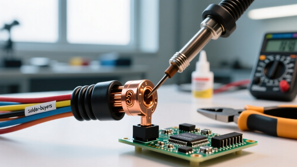
- Closed-Barrel (Tubular) Terminals: These feature a seamless or brazed copper tube. They are mandatory for soldering because the tubular shape acts as a reservoir, allowing flux to activate and solder to flow via capillary action without leaking onto the mating surface.
Material Selection: Copper vs. Brass
Always specify electrolytic tough pitch (ETP) copper terminals with a minimum tin plating of 100 micro-inches. Brass or steel-core terminals have significantly higher electrical resistance and will act as a bottleneck in high-current DC circuits, generating excess heat under continuous load.
Insulation Matrix: Choosing the Right Heat Shrink
The termination does not end at the solder joint. Environmental sealing and strain relief are critical safety components. Below is a comparison of common insulation methods for soldered terminals.
| Insulation Type | Moisture Seal | Strain Relief | Max Temp Rating | Safety Verdict |
|---|---|---|---|---|
| Pre-Insulated Vinyl (Nylon) | None | Poor | 105°C (221°F) | AVOID: Melts easily during soldering; traps corrosive flux fumes inside. |
| Standard Single-Wall Heat Shrink | Poor | Moderate | 135°C (275°F) | FAIR: Good for indoor, dry environments. Wicks moisture via capillary action in marine use. |
| Dual-Wall Adhesive Heat Shrink (3:1) | Excellent | Excellent | 125°C (257°F) | MANDATORY: Hot-melt adhesive seals out water and provides rigid strain relief. |
Step-by-Step Soldering Protocol for 10 AWG to 4 AWG Terminals
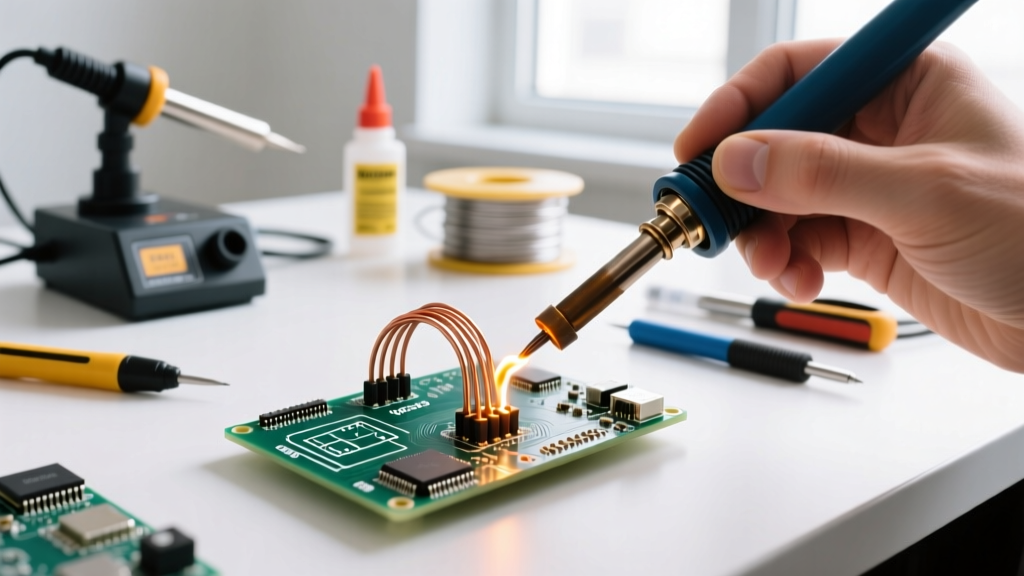
High-mass wires require high-thermal-capacity tools. A standard 40W pencil iron will result in cold joints. Use a temperature-controlled station like the Hakko FX-888D or Weller WE1010NA equipped with a heavy chisel tip (e.g., T18-D24 or equivalent 1/4" tip).
- Preparation: Strip the wire using precision strippers (e.g., Knipex ErgoStrip). Do not nick the copper strands; a nicked strand reduces the wire's ampacity and creates a mechanical weak point.
- Pre-Positioning: Slide the dual-wall adhesive heat shrink onto the wire before inserting the terminal. Ensure it is pushed back at least 4 inches to avoid premature shrinking from ambient heat.
- Flux Application: Even if using flux-cored solder, apply a small amount of liquid rosin-activated (RA) flux to the bare wire strands to break down heavy oxidation common in DC battery cables.
- Thermal Transfer: Set your iron to 380°C (716°F). Apply the flat face of the chisel tip directly to the copper barrel, not the wire. Heat the terminal for 3–5 seconds until the flux sizzles.
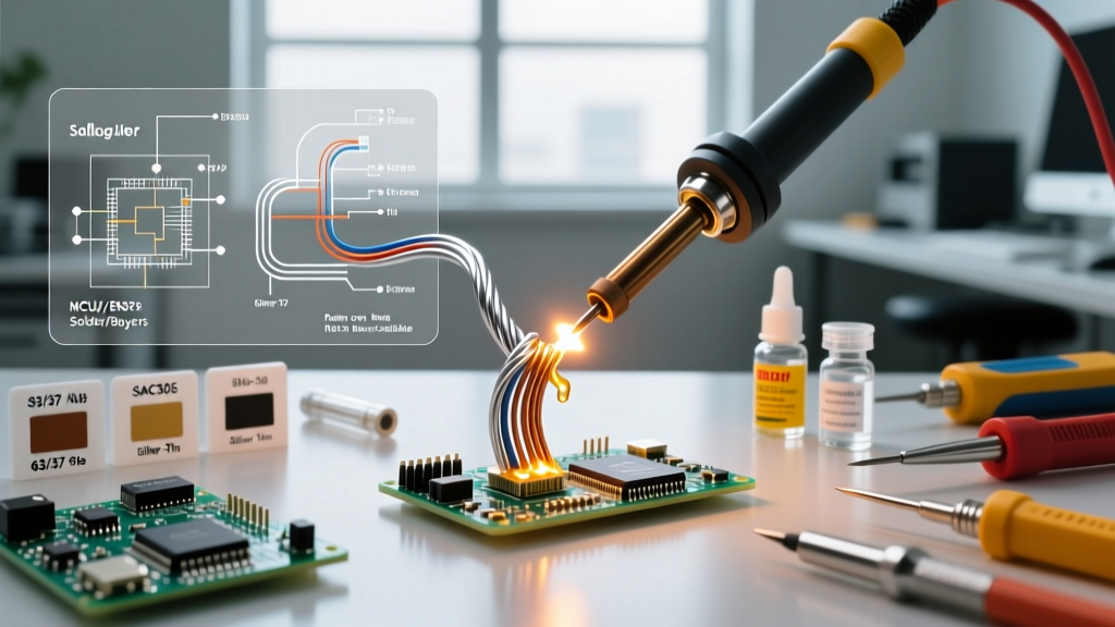
- Solder Feeding: Feed 63/37 Sn/Pb eutectic solder (0.031" diameter) into the wire-entry side of the barrel. The eutectic alloy melts and solidifies at a single temperature (183°C), preventing cold joints caused by movement during the plastic phase of 60/40 solder.
- Capillary Verification: Look for the solder to wick completely through the barrel and form a smooth, concave fillet at the wire entrance. Stop feeding immediately to prevent a 'solder ball' that can interfere with the heat shrink seal.
- Cooling: Remove the iron and hold the wire perfectly still for 10 seconds. Never blow on the joint; rapid cooling causes micro-fractures in the crystalline structure.
Critical Failure Mode: The 'Solder Wick' Effect
Expert Warning: Capillary action doesn't stop at the terminal barrel. If solder wicks up into the flexible strands of the wire, it turns a flexible copper rope into a rigid, brittle metal rod.
In any environment with minor vibration or thermal expansion/contraction, this rigid section will flex against the remaining flexible wire. Over time, the copper strands will work-harden and snap precisely at the boundary line, causing an open circuit or high-resistance arcing inside the insulation.
How to Prevent the Solder Wick Effect
- Control Solder Volume: Use only enough solder to fill the terminal barrel. Excess solder will inevitably wick into the wire.
- The 'Hinge' Gap: When positioning your heat shrink, leave a precise 1/16-inch (1.5mm) gap between the end of the terminal barrel and the start of the heat shrink. This exposes a tiny section of unsoldered, flexible wire, acting as a mechanical hinge that absorbs stress.
Crimping vs. Soldering: What the Standards Say
It is vital to understand the regulatory landscape. The American Boat & Yacht Council (ABYC E-11 standard) and SAE J1128 heavily favor gas-tight mechanical crimps for marine and automotive environments due to extreme vibration. Solder is explicitly forbidden as the sole mechanical support in these standards.
However, the IPC/WHMA-A-620 standard for cable assemblies provides strict criteria for soldered terminals in commercial, aerospace, and static industrial applications. If you are building a stationary solar battery bank or an indoor inverter setup, soldered terminals with proper adhesive heat shrink are entirely safe, code-compliant, and offer lower initial contact resistance than crimping.
Visual Inspection Criteria (IPC-A-610 Standards)
Once the joint has cooled and the heat shrink is applied (using a heat gun at 300°F, never the soldering iron), inspect the exposed wire fillet against professional acceptance criteria:
- Wetting Angle: The solder should meet the wire and terminal at a sharp angle (less than 90 degrees), indicating proper metallurgical bonding. A rounded, bulbous shape indicates a cold joint or insufficient flux.
- Insulation Clearance: The wire insulation should not be melted or charred. There must be a visible gap between the insulation jacket and the solder fillet to allow for visual inspection and to prevent dielectric breakdown.
- Surface Finish: The solder should appear shiny and smooth (for Sn/Pb) or slightly dull and satin (for SAC305 lead-free). Grainy or matte finishes on Sn/Pb indicate the joint was disturbed during solidification.
Essential Tooling and Material Budget (2026 Pricing)
Building safe soldered terminals requires an upfront investment in proper tooling. Do not compromise on these items:
- Soldering Station: Hakko FX-888D or Weller WE1010NA ($110 - $140). Must have digital temp control and interchangeable heavy-duty tips.
- Solder: Kester 44 Rosin-Core, 63/37 Sn/Pb, 0.031" ($35 per 1lb spool). Avoid plumbing-grade acid-core solder at all costs; it will corrode copper wires from the inside out within months.
- Heat Shrink: Ancor Marine Grade or 3M MFP-300 Dual-Wall Adhesive 3:1 ratio ($25 - $40 per spool). The 3:1 shrink ratio ensures it tightly grips both the thick terminal barrel and the thinner wire insulation.
- Heat Gun: Seekone 1800W with a deflector nozzle ($30) for evenly shrinking the adhesive tubing without scorching the polyolefin.
Summary
Soldered terminals, when executed with closed-barrel copper components, eutectic solder, and dual-wall adhesive heat shrink, provide a robust, low-resistance connection ideal for high-current DC systems. By avoiding the solder wick effect, maintaining strict temperature control, and adhering to IPC visual inspection standards, you ensure your electrical infrastructure remains safe, efficient, and fire-free for decades.