
The Thermodynamics of the 'Soldering Not Melting' Phenomenon
Every electronics hobbyist and professional technician eventually encounters the frustrating scenario of soldering not melting despite the iron being set to the correct temperature. You apply a 63/37 leaded wire (melting point 183°C) to a pad, your iron is dialed to 350°C, yet the solder simply rolls off the tip like water on a hot skillet. This is rarely a failure of the solder alloy itself; rather, it is a fundamental breakdown in thermal transfer dynamics.
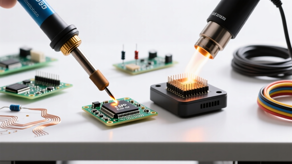
According to the thermal profiling guidelines outlined in IPC J-STD-001, a successful solder joint requires the pad, the component lead, and the solder to reach thermal equilibrium simultaneously. When solder refuses to melt, you are witnessing a thermal mass deficit: the copper ground plane or component mass is dissipating heat faster than your chosen method can deliver it. To solve this, we must compare the three primary thermal delivery methods—conduction, convection, and induction—and understand when each fails or succeeds.
Method 1: Traditional Conduction (Contact Soldering)
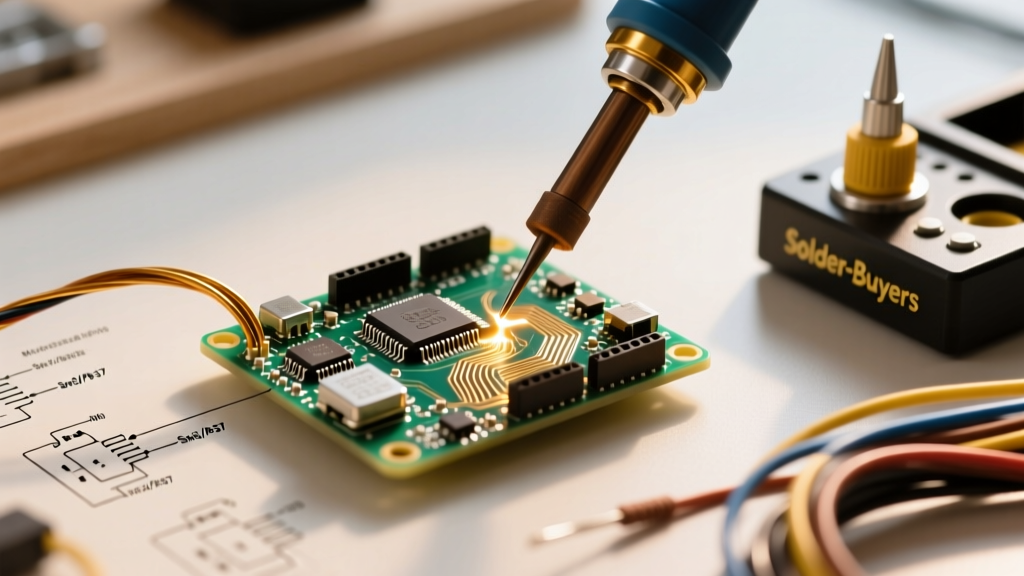
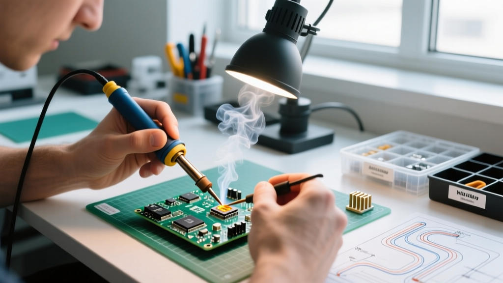
Conduction relies on direct physical contact between a heated metal tip and the workpiece. Standard workhorses like the Hakko FX-888D (70W, ~$115) or the Weller WE1010NA (70W, ~$135) dominate this space in 2026.
Why Solder Fails to Melt Here
The primary failure mode in contact soldering is tip geometry mismatch and thermal sinking. If you attempt to solder a DPAK component with an exposed thermal ground tab using a fine conical tip (like the Hakko T18-B), the microscopic contact area cannot transfer sufficient joules of energy. The PCB's internal copper layers (which boast a thermal conductivity of roughly 401 W/m·K) act as a massive heat sink, pulling thermal energy away from the pad. The solder wire touches the pad, but the pad remains below 183°C, resulting in the dreaded 'soldering not melting' effect.
- Best For: Standard through-hole components, 0805/0603 SMDs, and low-thermal-mass wires.
- Failure Point: Large ground planes, heavy gauge wire (e.g., 10 AWG XT60 connectors), and multi-layer RF boards.
Method 2: Forced Convection (Hot Air Rework)
When contact conduction fails due to thermal mass, forced convection bypasses the physical contact limitation by heating the ambient air and the entire component simultaneously. Stations like the Quick 861DW (1200W, ~$260) utilize a brushless fan to push air across a ceramic heating element.
Why Solder Fails to Melt Here
Hot air solves the ground-plane heat-sink issue by blanketing the entire pad and component in 380°C air, raising the baseline temperature of the PCB locally. However, solder will still fail to melt if the airflow velocity is too high or the nozzle is improperly sized. If you use a 4mm nozzle on a large QFN chip, the air cools rapidly before penetrating to the center thermal pad. Furthermore, without the mechanical friction of a physical iron tip to break through surface oxidation, hot air relies entirely on chemical flux activation to allow the solder to wet the pad.
- Best For: QFNs, BGAs, multi-pin SOICs, and shrinking heat-shrink tubing.
- Failure Point: Extremely dense boards where adjacent plastic connectors might melt, or heavily oxidized pads lacking aggressive flux.
Method 3: High-Frequency Induction (SmartHeat Technology)
Induction soldering represents the pinnacle of thermal recovery. Systems like the Metcal MX-5200 (~$850) do not use a traditional resistive ceramic heater. Instead, an RF generator sends a high-frequency alternating current through a coil in the handpiece, inducing eddy currents directly into the ferromagnetic tip.
The Ultimate Solution to Thermal Sinking
When an induction tip touches a massive ground plane and the temperature drops, the tip's magnetic permeability changes, causing the RF generator to instantly dump more power into the tip to maintain the exact Curie temperature. As detailed in Metcal's SmartHeat technology documentation, this means the iron never 'runs out' of heat. If your solder is not melting on an induction system, it is almost certainly a severe oxidation issue or an entirely incorrect alloy choice, not a thermal mass deficit.
Comparative Analysis: Overcoming Thermal Mass Deficits
| Method | Heat Transfer Mechanism | Typical Wattage (2026) | Avg. Cost | Why Solder Fails to Melt |
|---|---|---|---|---|
| Conduction (Standard) | Direct physical contact | 60W - 80W | $100 - $150 | Tip too small; ground plane sinks heat faster than heater can replenish. |
| Convection (Hot Air) | Heated air circulation | 800W - 1200W | $150 - $300 | Airflow too high/cool; lack of flux to break oxidation barrier. |
| Induction (RF) | Molecular eddy currents | 60W - 80W (Dynamic) | $700 - $1,000 | Tip heavily oxidized; wrong Curie point cartridge selected for the alloy. |
Expert Insight: When soldering heavy battery tabs or 8 AWG silicone wire, never rely on temperature alone. The NASA-STD-8739.3 workmanship manual emphasizes that dwell time and thermal preparation are critical. Pre-tinning both the wire and the terminal with aggressive rosin flux before attempting the final joint reduces the required thermal transfer time by up to 60%, preventing the solder from rolling off in beads.
The Chemical Variable: Flux Activation vs. Oxidation
Often, the diagnosis of 'soldering not melting' is actually a misdiagnosis of soldering not wetting. The solder is technically melting (transitioning from solid to liquid), but surface tension and copper oxide prevent it from adhering to the pad, causing it to ball up and roll away.
In 2026, the shift toward lead-free SAC305 alloys (melting at 217°C) has exacerbated this. SAC305 has a higher surface tension and a narrower plastic range than 63/37. If your iron tip is coated in a black, crusty layer of burned rosin, thermal transfer drops by over 85%.
Actionable Flux Protocol
- Clean the Tip: Use brass wool (never a wet sponge, which causes thermal shock and micro-fractures in the iron plating).
- Apply External Flux: Do not rely solely on the flux core inside your solder wire. Apply a tacky no-clean flux like Amtech NC-559-V2-TF or a liquid rosin like Kester 951 directly to the pad.
- Re-tin Immediately: Melt a small amount of fresh, leaded solder onto the tip to create a thermal bridge before touching the workpiece.
4-Step Diagnostic Protocol for Stubborn Joints
If you are staring at a joint where the soldering is not melting, follow this exact diagnostic sequence before turning up your iron's temperature (which risks delaminating the PCB pads).
Step 1: Verify the Alloy and Temperature Delta
Check your solder wire spool. Are you using SAC305 (Lead-Free) while your iron is set to 300°C? SAC305 requires a tip temperature of at least 350°C to 380°C for proper wetting. Conversely, if using 63/37, drop the iron to 320°C to prevent burning the internal flux core before it can activate.
Step 2: Maximize Contact Area (The Geometry Fix)
Swap your fine-point tip for a heavy chisel or bevel tip. For Hakko FX-888D users, switch to the T18-D24 (2.4mm chisel) or the T18-C4 (4mm bevel). The bevel tip allows you to 'cup' the component lead, increasing the surface area contact by up to 300% compared to a conical tip, dramatically increasing thermal transfer.
Step 3: Introduce a Thermal Bridge
If the pad is still acting as a heat sink, apply a blob of fresh solder to the iron tip, and immediately press that molten blob against the stubborn pad. The liquid solder acts as a highly conductive thermal bridge, transferring heat into the copper pad much faster than solid metal-to-metal contact.
Step 4: Escalate to Convection or Pre-heating
If the thermal bridge fails, the board's thermal mass is simply too high for a hand iron. Place the PCB on a PCB pre-heater (like the Hakko FR-830) set to 120°C to raise the baseline temperature of the entire board, or switch to a hot air station at 350°C with 40% airflow to blanket the joint in heat.
Conclusion
The 'soldering not melting' problem is rarely a mystery; it is a predictable outcome of physics and chemistry. By understanding the limitations of standard conduction irons when facing heavy ground planes, and knowing when to escalate to hot air convection or RF induction, you can eliminate cold joints and pad damage. Always prioritize tip geometry and flux chemistry over brute-force temperature increases, ensuring your 2026 workbench produces joints that meet the highest aerospace and commercial reliability standards.