
The Metallurgy of a Perfect Joint: Beyond 'Electronic Glue'
When soldering a circuit board, beginners often mistake solder for a simple conductive adhesive. In reality, it is a complex metallurgical bonding process. A reliable connection relies on the formation of an Intermetallic Compound (IMC) layer—typically Cu6Sn5 when using tin-based alloys on copper pads. This microscopic layer is what creates the actual electrical and mechanical bond. If the thermal profile is incorrect, the IMC layer either fails to form (resulting in a cold joint) or grows too thick and brittle (causing micro-fractures under thermal cycling).
According to the IPC Standards for Electronic Assemblies, specifically IPC-A-610, a pristine through-hole joint must exhibit a smooth, concave fillet with excellent wetting, covering at least 270 degrees of the pad for Class 2 (Standard) products, and 360 degrees for Class 3 (High-Reliability) aerospace or medical devices.
Selecting Your Arsenal: Modern Equipment Breakdown
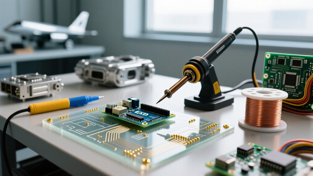
The market for soldering equipment has evolved significantly. You no longer need to spend $300 on a bench station to achieve professional thermal recovery. Here is what you need in your toolkit today:
1. The Soldering Station
- Hakko FX-888D (~$115): The undisputed workhorse for benchtop use. It features a digital display, password-protected temperature locking, and uses the widely available T18 tip series. Its 70W ceramic heater provides excellent thermal recovery for heavy ground planes.
- Pine64 Pinecil V2 (~$55): A revolutionary portable option powered by a RISC-V chip. It supports USB-C PD3.1 (up to 245W) and DC barrel inputs. It heats to 350°C in under 6 seconds and uses inexpensive, high-quality TS100/Pine64 compatible tips.
2. Solder Alloys and Wire Gauges
Choosing the right alloy and diameter is critical for capillary action and heat transfer.
- Leaded (Sn63/Pb37): The eutectic standard (e.g., Kester 245). It melts at exactly 183°C with no plastic phase, preventing disturbed joints. Use 0.031" (0.8mm) diameter for standard through-hole components and 0.015" (0.4mm) for fine-pitch SMD work.
- Lead-Free (SAC305): Composed of 96.5% Tin, 3% Silver, and 0.5% Copper. It requires higher operating temperatures (melting point ~217°C) and wets slightly slower. Mandatory for commercial manufacturing, but less forgiving for hobbyists.
3. Flux Chemistry
Flux removes copper oxidation and lowers surface tension. For manual rework, a Rosin Mildly Activated (RMA) or a high-quality No-Clean (NC) tacky flux (like Amtech NC-559-V2-TF) is essential. Never use plumbing acid flux on a PCB; it is highly corrosive and will destroy copper traces within weeks.
The 5-Step Execution Protocol
Professional assemblers follow a strict sequence to ensure optimal wetting and minimize thermal stress on sensitive silicon. Refer to the foundational techniques outlined in SparkFun's Through-Hole Soldering Guide for visual references on iron angling.
- Mechanical Preparation: Clean the PCB pads and component leads with 99% Isopropyl Alcohol (IPA) and a lint-free swab. Ensure the component is mechanically secured (using a helping-hands tool or Kapton tape) so it cannot move during solidification.
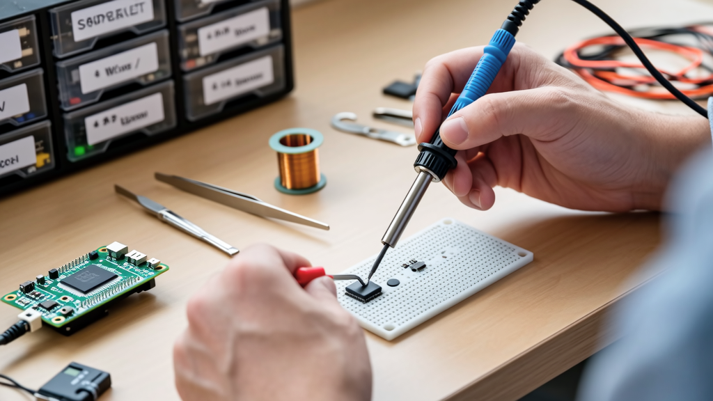
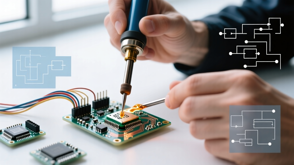
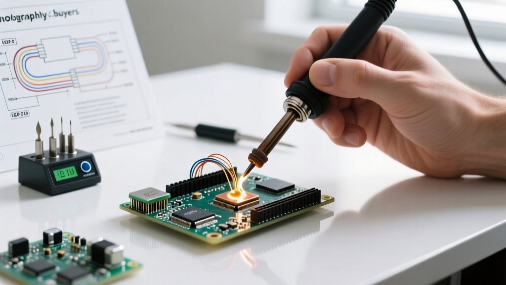
- Thermal Bridging: Apply the iron tip so it simultaneously touches the component lead and the PCB pad. Hold for 1 to 1.5 seconds to raise both surfaces above the solder's liquidus temperature.
- Feed the Solder: Apply the solder wire to the opposite side of the joint from the iron tip. If the solder melts on the iron and flows to the pad, you have insufficient heat transfer and risk a cold joint.
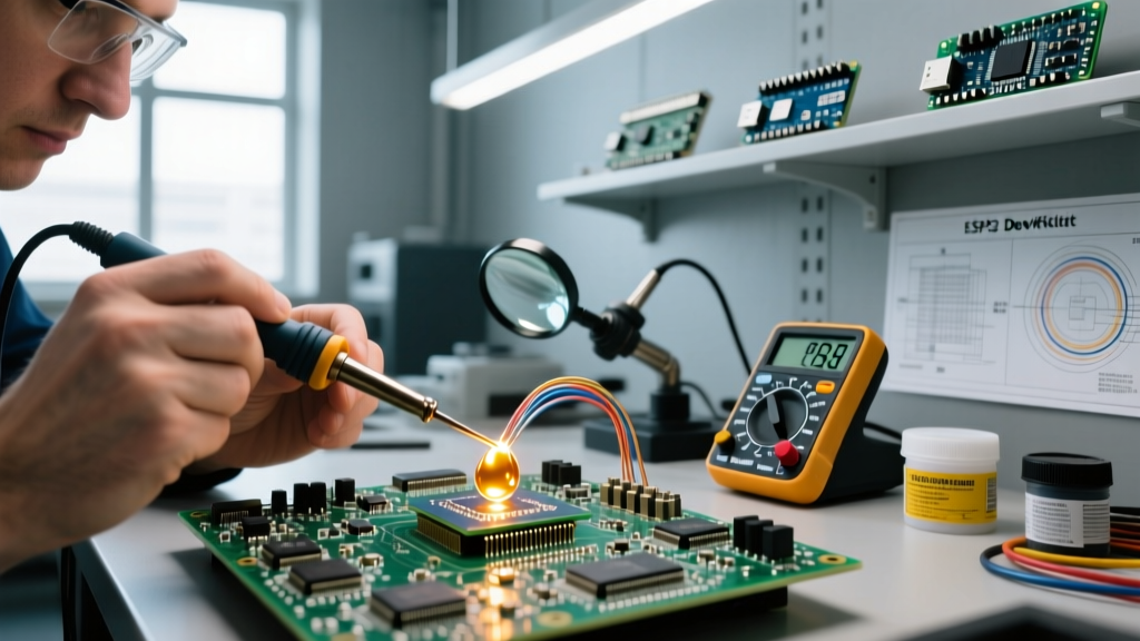
- Reflow and Wet: Allow the solder to flow into the via or around the lead. A standard THT joint should take no more than 2 to 3 seconds total. The flux should bubble and activate, leaving a shiny, concave fillet.
- Controlled Withdrawal: Remove the solder wire first, then sweep the iron tip away at a 45-degree angle to create a clean peak and avoid leaving a solder icicle.
Thermal Profiles: Component Mass vs. Iron Temperature
Setting your iron to a static 400°C is a recipe for lifted pads and degraded flux. Adjust your temperature based on the thermal mass of the joint.
| Component Type | Recommended Iron Temp (Sn63/Pb37) | Dwell Time | Tip Geometry |
|---|---|---|---|
| 0805 / 0603 SMD Passives | 320°C - 340°C | 1 - 2 seconds | Micro Pencil / Chisel (1.0mm) |
| Standard THT (Resistors, DIP ICs) | 350°C | 2 - 3 seconds | Standard Chisel (2.4mm) |
| Heavy Connectors / Large Electrolytics | 360°C - 380°C | 3 - 4 seconds | Wide Chisel / Bevel (3.2mm+) |
| Multi-Layer Ground Planes | 380°C + Board Preheating | 4 - 5 seconds | Heavy Duty Chisel / Knife |
Diagnosing and Resolving Common Failure Modes
Even experienced engineers encounter defects. Here is how to identify and fix the most common issues when soldering a circuit board:
Cold Joints
Symptoms: The joint appears dull, grainy, or bulbous rather than smooth and concave.
Cause: Insufficient heat applied to the pad, or the component was moved before the solder fully crystallized.
Resolution: Apply fresh liquid or tacky flux. Re-heat the joint with a clean, properly tinned tip until the solder flashes to a liquid mirror finish, then hold perfectly still until it solidifies.
Solder Bridges (Shorts)
Symptoms: Solder connects two adjacent pins, commonly seen on SOIC or QFP IC packages.
Cause: Using solder wire that is too thick, or an iron tip that is too wide for the pitch.
Resolution: Do not try to 'wipe' the bridge away with the iron. Apply a generous amount of no-clean flux. Place a 0.050" (1.27mm) copper desoldering braid (such as MG Chemicals or Chemtronics) over the bridge, and press the iron down onto the braid. Capillary action will wick the excess solder away instantly.
Pad Lifting and Delamination
Symptoms: The copper pad peels away from the FR4 fiberglass substrate.
Cause: Excessive dwell time (holding the iron for >5 seconds) or using excessive downward pressure.
Resolution: Prevention is the only cure. If a pad lifts, you must abandon the via and route a 'dead bug' jumper wire using 30 AWG Kynar wire to the next available trace or via, securing it with UV-curable solder mask or cyanoacrylate.
Tip Maintenance and Oxidation Prevention
A soldering iron tip that is black and crusty has zero thermal conductivity. Oxidation acts as a thermal insulator.
Pro-Tip: Never use a wet cellulose sponge to clean your tip. The rapid thermal shock causes micro-cracking in the iron plating, leading to pitting and tip death. Always use a dry brass wire sponge.Keep your tip heavily tinned with a thick layer of solder when powering down. This sacrificial layer oxidizes instead of the iron's protective plating. If a tip becomes heavily oxidized, use a specialized tip tinner (like Hakko 599B) which contains mild abrasives and aggressive flux to strip the oxidation and re-tin the surface simultaneously.
Fume Extraction and Respiratory Safety
The smoke generated when soldering a circuit board is not just harmless vapor; it consists of volatilized flux chemicals. Rosin (colophony) is a known respiratory sensitizer and can cause occupational asthma with prolonged, unprotected exposure. The UK Health and Safety Executive (HSE) Guidance on Soldering Fumes explicitly mandates local exhaust ventilation (LEV) for anyone soldering regularly.
At a minimum, invest in a dedicated fume extractor equipped with a HEPA filter and an activated carbon bed, such as the Hakko FA-400 (~$65) or a BOFA extraction unit for professional labs. Position the extraction nozzle exactly 2 to 3 inches from the soldering point to capture the plume before it enters your breathing zone. Relying on an open window or a standard desk fan is entirely insufficient and merely disperses the hazardous particulates across your workspace.