
The Magnification Dilemma in Modern PCB Rework
As surface-mount device (SMD) components shrink to 0402 and 0201 imperial sizes, the human eye can no longer reliably inspect or rework solder joints unaided. According to the IPC J-STD-001 standard for soldered electrical assemblies, visual inspection of micro-BGA and fine-pitch QFP components requires optical aids ranging from 3x to 10x magnification to meet Class 2 and Class 3 reliability requirements. But which optical method actually translates to better bench work?
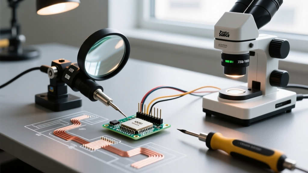
For hobbyists and professionals alike, the market offers three distinct magnification methods: the traditional optical soldering magnifying glass, the stereo binocular microscope, and the modern digital HDMI microscope. Each method fundamentally alters your hand-eye coordination, working distance, and susceptibility to flux fume interference. In this method comparison, we break down the exact physics, pricing, and practical edge cases of each approach to help you outfit your workbench for 2026 and beyond.
Method 1: The Optical Soldering Magnifying Glass
The optical soldering magnifying glass remains the entry-level standard for through-hole soldering and basic SMD work. Modern iterations have evolved far beyond simple handheld lenses, now featuring integrated LED halo rings and articulating gooseneck arms.
Hardware Spotlight: Donegan DA-10 & Fancii LED Halo
The Donegan Optical DA-10 (retailing around $35) utilizes a true optical glass lens rather than cheap acrylic, eliminating the severe chromatic aberration (color fringing) that plagues sub-$15 alternatives. For illuminated work, the Fancii LED Halo Magnifier ($25-$30) provides a 5500K daylight color temperature. This specific Kelvin range is critical; warmer 3000K lights wash out the subtle visual differences between a dull, cold solder joint and a shiny, properly wetted one.
The Physics and Limitations
The primary advantage of the soldering magnifying glass is zero latency and true binocular depth perception. Because you are viewing the PCB with both eyes through a single large focal plane, your brain naturally calculates the Z-axis distance between your soldering iron tip and the component pad.
However, the method is severely limited by fixed focal lengths. A standard 3x optical glass requires a working distance of exactly 8 to 10 inches. If your flux fume extractor nozzle gets in the way, or if you need to lean in to drag-solder a 0.5mm pitch TQFP chip, you are forced into awkward spinal contortions to maintain the focal sweet spot.
Method 2: Stereo Binocular Microscopes
When professionals talk about 'bench microscopes,' they are referring to stereo binocular microscopes. Unlike compound biological microscopes that look *through* a specimen, stereo microscopes use a Greenough optical design to bounce light *off* the surface of the PCB, providing a 3D stereoscopic image.
Hardware Spotlight: AmScope SM-4TZ
The AmScope SM-4TZ (priced between $380 and $450) is the undisputed workhorse of professional rework stations. It offers a continuous zoom range of 7x to 45x. Crucially, it features a 100mm (4-inch) working distance. This specific measurement is the industry gold standard because it provides enough physical clearance to comfortably maneuver a Hakko FX-951 or JBC CD-2BE soldering station handpiece, tweezers, and a fume extractor simultaneously without bumping the objective lens.
The Professional Edge
Stereo microscopes eliminate the 'tunnel vision' effect of single-lens magnifiers. The dual optical paths provide genuine depth perception, allowing you to see exactly when a soldering iron tip touches a microscopic via. The trade-off is cost, physical footprint (requiring a heavy boom stand to prevent tipping), and the need for a high-CRI (Color Rendering Index > 90) external ring light to prevent harsh shadows inside deep PCB vias.
Method 3: Digital HDMI Microscopes
Digital microscopes replace the optical eyepieces with a CMOS sensor, outputting the image to an LCD screen or external HDMI monitor. This method has surged in popularity due to plummeting sensor costs and the rise of high-refresh-rate displays.
Hardware Spotlight: Andonstar AD246S-M
The Andonstar AD246S-M ($220-$260) features a 10-inch built-in screen and outputs 1080p at 60fps. It includes an integrated metal thermal shield to protect the lens from the radiant heat of a soldering iron. For rework technicians who need to record their process for quality assurance or YouTube tutorials, the digital method is the only viable option.
The Latency Trap
The fatal flaw of the digital method for precision soldering is sensor-to-screen latency. Even at 60fps, there is an inherent processing delay of 30 to 50 milliseconds. When drag-soldering a 64-pin QFP chip, this micro-delay causes a phenomenon known as 'visual drift.' Your hand moves the iron, but the screen updates a fraction of a second later, leading to accidental bridging of adjacent pins. Furthermore, staring at a 2D screen completely destroys your Z-axis depth perception, forcing you to rely entirely on focus-blur cues to judge the height of your iron tip.
Head-to-Head Comparison Matrix
| Feature | Optical Magnifying Glass | Stereo Binocular Microscope | Digital HDMI Microscope |
|---|---|---|---|
| Magnification Range | 1.5x - 5x (Fixed) | 7x - 45x (Continuous Zoom) | 10x - 300x (Digital Zoom) |
| Depth Perception | Moderate (Monocular focus) | Excellent (True Stereoscopic 3D) | Poor (2D Screen) |
| Latency | Zero (Speed of Light) | Zero (Speed of Light) | 30ms - 50ms (Sensor Delay) |
| Working Distance | 8 - 12 inches | 4 - 6 inches (Standard) | 2 - 5 inches |
| Avg. Cost (2026) | $25 - $60 | $350 - $600+ | $150 - $300 |
| Best Application | Through-hole, basic 0805 SMD | 0402 SMD, BGA rework, micro-soldering | Inspection, recording, PCB tracing |
Hidden Variables: Flux Fumes and Ergonomics
When choosing a magnification method, most buyers ignore the physical realities of the soldering environment: flux condensation and spinal health.
The Flux Condensation Problem
When you heat rosin-based or no-clean flux, it vaporizes and immediately condenses on the nearest cool surface. With a stereo binocular microscope, this sticky residue coats your expensive objective lens within weeks, degrading optical clarity. Professionals must install a sacrificial UV filter or a cheap glass watch-crystal over the lens to catch the flux. Conversely, digital microscopes and optical magnifying glasses are much easier to wipe down, and digital screens are entirely immune to flux buildup.
Ergonomics and Neck Strain
According to the CDC's NIOSH guidelines on ergonomics, sustained static neck flexion (looking down) is a primary driver of cervical spine disorders in assembly workers. An optical soldering magnifying glass placed flat on a desk forces you to hunch over at a 45-degree angle. A properly mounted stereo microscope on a boom arm allows you to sit upright and look straight ahead into the eyepieces, drastically reducing long-term musculoskeletal fatigue. If you solder for more than two hours a day, ergonomics must dictate your purchase.
Final Verdict: Choosing Your Magnification Method
There is no universal 'best' method; the correct choice depends entirely on your component scale and workflow.
- Choose the Optical Soldering Magnifying Glass if: You primarily solder through-hole components, large terminal blocks, or 0805/1206 SMDs. It is cheap, requires zero calibration, and provides adequate lighting for basic hobbyist projects.
- Choose the Stereo Binocular Microscope if: You are performing professional PCB rework, dealing with 0402 components, repairing smartphones, or drag-soldering fine-pitch ICs. The true 3D depth perception and zero latency are non-negotiable for preventing thermal damage to sensitive silicon.
- Choose the Digital HDMI Microscope if: Your primary goal is visual inspection, PCB reverse-engineering, tracing micro-vias, or recording your work for content creation. Avoid it for active, high-precision soldering due to latency-induced hand drift.
Frequently Asked Questions
Can I use a jeweler's loupe instead of a soldering magnifying glass?
No. Jeweler's loupes (typically 10x to 30x) require a working distance of less than one inch. Bringing your face and a flammable plastic loupe one inch away from a 400°C soldering iron tip is a severe burn and fire hazard. Always use magnification tools designed with a minimum 4-inch working distance for thermal safety.
Do I need a polarizing filter for my microscope?
Yes, if you are inspecting glossy PCBs or freshly cleaned flux residues. A polarizing filter (placed over both the LED ring light and the microscope objective) eliminates the harsh white glare from the board's solder mask, allowing you to clearly see the actual grain structure of the solder joint and identify micro-cracks.