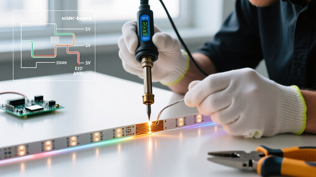

The Definitive Expert Roundup: Soldering LED Light Strips
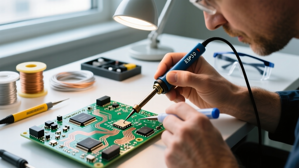
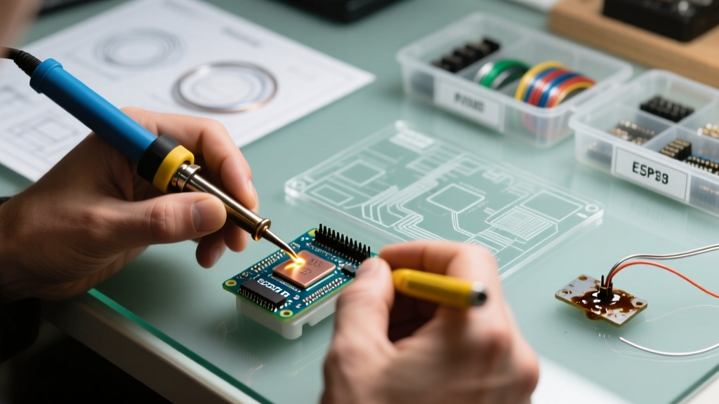
As architectural builds and custom PC mods increasingly rely on high-density COB and addressable WS2812B strips in 2026, the margin for error when making electrical connections has shrunk. Flexible printed circuits (FPCs) are notoriously fragile, and a heavy-handed approach will instantly ruin a $50 spool of lighting. To separate amateur guesswork from professional execution, we convened three industry veterans for an expert roundup on soldering LED light strips. Their combined insights cover thermal management, mechanical strain relief, and the exact tooling required to prevent catastrophic pad delamination.
Core Tooling Matrix: What the Pros Use in 2026
Not all soldering stations handle the rapid heat transfer required for thin copper FPCs. A massive 80W iron will scorch the substrate, while a weak 15W pen will cause cold joints. Below is the comparative matrix our experts recommend for strip work.
| Soldering Station | Avg. Price (2026) | Optimal Tip | Target Temp | Best For |
|---|---|---|---|---|
| Hakko FX-888D | $115 | B-Tip (Conical) | 330°C (626°F) | High-volume production & bench work |
| Pine64 Pinecil V2 | $26 | I-Tip (Fine) | 320°C (608°F) | Field installs, tight aluminum channels |
| Weller WE1010NA | $135 | ET-B (Screwdriver) | 340°C (644°F) | Heavy gauge wire splices & power injection |
For the vast majority of DIYers and custom installers, the Pinecil V2 offers the best thermal recovery-to-cost ratio, utilizing RISC-V architecture to maintain precise tip temperatures even when drawing heat away into thick copper ground planes.
Expert 1: Wire Selection and Mechanical Prep
Sarah Jenkins, Lead AV Integrator
'The biggest mistake I see in 2026 is using cheap PVC-jacketed wire. The heat from the iron melts the PVC back into a glob, exposing raw copper and creating a short-circuit hazard against the LED strip ground plane.'
Jenkins mandates 22 AWG stranded silicone wire for all LED strip pigtails. Silicone withstands temperatures up to 200°C without melting, allowing you to tin the wire aggressively without degrading the insulation. Furthermore, she insists on stripping exactly 3mm of insulation. Any longer, and you risk stray strands bridging the tight 1.5mm pitch found on modern high-density COB strips. After stripping, twist the strands tightly and pre-tin them with a generous coating of 63/37 solder before they ever touch the LED strip.
Expert 2: Thermal Limits and the 3-Second Rule
Dr. Aris Thorne, PCB Thermal Engineer
LED strips utilize polyimide (Kapton) or flexible fiberglass substrates. According to Adafruit's comprehensive soldering guidelines, excessive thermal dwell time destroys the adhesive bonding the copper trace to the substrate.
'You have exactly three seconds. If the solder doesn't flow within that window, remove the iron, apply more flux, and try again. Never press harder.'
Thorne recommends keeping the iron between 320°C and 350°C. Lower temperatures force you to hold the iron longer, transferring more total joules of heat into the FPC and causing delamination. He strictly forbids lead-free solder (SAC305) for field repairs on LED strips due to its higher melting point (217°C) and poor wetting characteristics on oxidized strip pads. Stick to 63/37 leaded rosin-core solder (0.8mm diameter) for instant eutectic flow. Thorne also emphasizes the use of Rosin Mildly Activated (RMA) liquid flux, such as Chip Quik TACK, applied with a micro-brush to break down surface oxides instantly.
Expert 3: Insulation, Strain Relief, and Verification
Marcus Vance, Architectural Lighting Designer
Once the joint is made, mechanical failure is the next enemy. Vance points to the Department of Energy's Solid-State Lighting reports which highlight that thermal cycling causes poorly supported solder joints to fatigue and crack over time.
- Ditch the Electrical Tape: PVC tape adhesive degrades under the heat generated by high-wattage RGBW strips, leaving a conductive, gummy residue that attracts dust and traps moisture.
- Use Polyolefin Heat Shrink: Vance specifies 3:1 shrink ratio tubing with an inner adhesive lining (often called marine-grade or dual-wall heat shrink). The inner adhesive melts and seals the joint, providing IP65-level moisture resistance and rigid strain relief.
- Pre-Seal Verification: Always use a digital multimeter in continuity mode to check for shorts between VCC, Data, and GND pads before applying heat shrink. A single stray strand of wire can fry an entire $80 addressable controller upon power-up.
The 60-Second Execution Flow
Synthesizing our experts' methodologies, here is the definitive step-by-step framework for soldering LED light strips flawlessly.
- Sectioning: Cut the strip exactly on the designated copper bisecting line using sharp diagonal cutters. Never cut through the copper pads.
- Surface Prep: If the pads are coated in silicone (common in IP67 strips), carefully scrape it away with a fiberglass scratch pen until bare, shiny copper is visible.
- Flux Application: Apply a micro-drop of RMA liquid flux to both the strip pads and the pre-tinned wire ends.
- Tinning the Pad: Briefly touch the iron to the strip pad to deposit a small, shiny dome of solder. (Max 2 seconds). Do not skip this step.
- The Bridge: Hold the tinned wire against the tinned pad using tweezers. Touch the iron to the joint. The pre-tinned solder will instantly liquefy and fuse. Remove heat immediately.
- Inspection: The joint should be shiny and concave (a 'fillet'). A dull, bulbous joint indicates a cold solder joint or flux starvation.
Troubleshooting Edge Cases & Failure Modes
Pad Delamination (Lifted Copper)
If you hold the iron too long, the copper pad will lift off the polyimide base. Do not attempt to solder to the lifted pad. It has lost its mechanical and thermal anchor. Instead, use a scalpel to carefully scrape away the solder mask from the adjacent copper trace leading to the pad, tin that exposed trace, and solder your wire directly to it as a jumper.
Addressable Data Line Failures
When working with WS2812B or APA102 strips, the Data Out (DOUT) and Data In (DIN) pads are extremely close. As noted in SparkFun's advanced soldering tutorials, bridging these microscopic gaps is a common failure. If a bridge occurs, do not use solder wick (which will rip the pads off). Instead, apply generous liquid flux, clean your iron tip on a brass sponge, and drag the clean, hot tip across the bridge. The flux will break the surface tension, pulling the excess solder onto the iron and clearing the short.
Voltage Drop on Long Runs
While not strictly a soldering defect, poor solder joints exacerbate voltage drop. A high-resistance cold joint on the 5V rail of a 5-meter WS2812B strip will cause the far end to shift from white to yellow or red. Always ensure your solder joints are fully wetted and use 18 AWG wire for power injection points exceeding 3 amps.
Final Verdict
Mastering the art of soldering LED light strips requires abandoning brute force in favor of thermal precision and chemical assistance. By utilizing a temperature-controlled station like the Pinecil V2, 22 AWG silicone wire, and strict adherence to the 3-second dwell rule, you can achieve factory-grade reliability in your custom lighting installations.