
Introduction to Soldering Cup Safety and Precision
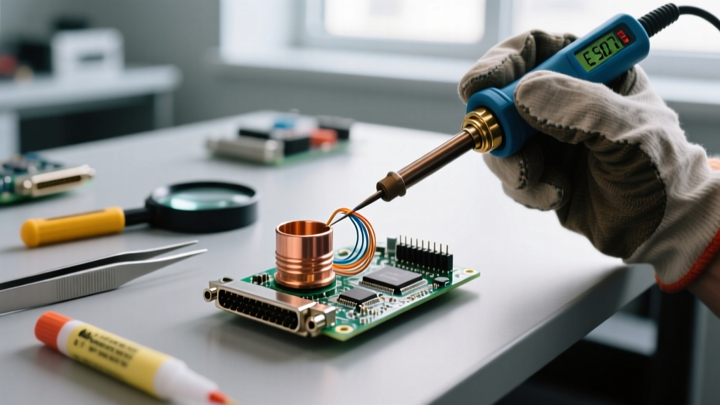
A soldering cup is a specialized cylindrical terminal cavity found on a wide variety of electrical connectors, including D-Subminiature (D-Sub) interfaces, Mil-Spec circular connectors (such as the Amphenol PT and MS series), and heavy-duty toggle switches. Unlike printed circuit board (PCB) through-hole pads or crimp lugs, a solder cup presents a unique three-dimensional challenge: it is essentially a blind hole that must be filled with molten solder while simultaneously accepting a stripped wire. As we navigate the 2026 manufacturing and DIY landscape, the push toward lead-free (SAC305) assemblies and higher-density connectors has made soldering cup termination more thermally demanding than ever.
Improper technique in a solder cup does not merely result in a weak mechanical bond; it introduces severe safety hazards. These range from toxic colophony fume inhalation and molten solder splatters to catastrophic dielectric meltdowns that can cause high-voltage arcing in aerospace or automotive applications. This guide details the rigorous safety protocols, thermal management strategies, and precise methodologies required to master solder cup terminations while adhering to modern industry standards.
The Hidden Hazards of Solder Cup Termination
Before applying heat, technicians must understand the specific failure modes and safety risks inherent to the solder cup geometry. According to guidelines referenced by NASA Electronic Parts and Packaging (NEPP), the blind-hole nature of these terminals creates distinct thermal and chemical traps.
1. Dielectric Meltdown and Insert Recession
The insulating inserts of most Mil-Spec and commercial connectors are manufactured from glass-filled thermoplastics like PBT (Polybutylene Terephthalate) or Nylon. These materials typically have a glass transition or melting point between 220°C and 260°C. If an operator applies a low-wattage iron for an extended period (exceeding 4–5 seconds), the heat conducts down the metal cup and softens the surrounding plastic. The cup can literally recede into the connector housing, ruining the terminal alignment and creating a severe short-circuit hazard when mated.
2. Flux Entrapment and Micro-Splatter
When flux is applied deep inside a solder cup and rapidly heated, the volatile solvents boil and expand. If the wire is inserted too quickly, or if the cup is entirely sealed by a blob of solder, the expanding gas has no escape route. This results in violent micro-splatters of molten solder and boiling flux ejecting from the cup, posing a direct burn hazard to the operator's hands and eyes, while also depositing conductive solder balls across adjacent pins.
3. Capillary Wicking and Insulation Shrinkback
If the wire strip length is too long, or if the iron is applied directly to the wire rather than the cup, molten solder will wick up the strands beneath the wire insulation. This capillary action makes the wire rigid and brittle, leading to fatigue fractures under vibration. Furthermore, excessive heat transfer to the wire causes the PTFE or PVC insulation to shrink back, exposing bare conductor and risking an electrical short against the connector shell.
Thermal Management and Tooling Calibration
The golden rule of solder cup safety is high thermal mass, short dwell time. You must transfer the required energy into the cup as rapidly as possible to melt the solder without giving heat time to migrate into the plastic dielectric.
- Soldering Station Selection: Avoid cheap, unregulated ceramic heaters. Invest in a high-wattage, closed-loop station like the Hakko FX-951 (typically $380–$420 in 2026) or the Weller WX2. These stations utilize active tip sensing to dump massive current into the heating element the moment the thermal load of the brass cup is detected.
- Tip Geometry: Never use a conical (pointed) tip for solder cups. Conical tips lack the surface area for efficient heat transfer, forcing the operator to hold the iron longer and melt the plastic. Use a heavy bevel or chisel tip, such as the Hakko T15-C3 or Weller RT4. The flat surface should mate perfectly with the outside curvature of the solder cup.
- Temperature Profiling: For traditional Sn63/Pb37 (leaded) solder, set the station to 350°C (662°F). For lead-free SAC305, you must elevate the temperature to 380°C–395°C (725°F–743°F). While this seems dangerously high for the plastic insert, the higher delta-T ensures the solder flows in under 2.5 seconds, paradoxically protecting the plastic from prolonged thermal soak.
Industry Standard Note: The IPC Standards (specifically IPC-A-610 and IPC-J-STD-001) dictate that a solder cup connection must exhibit a minimum of 25% side-fill visibility, with the wire fully embedded and the solder forming a smooth, concave meniscus. Overfilling the cup to the brim is considered a defect, as it prevents proper inspection and risks shorting to adjacent terminals.
Step-by-Step Safe Termination Protocol
Follow this precise sequence to ensure structural integrity and operator safety. Always wear ANSI-rated safety glasses to protect against flux splatter.
- Precision Stripping: Strip the wire to the exact depth of the solder cup minus 0.5mm. Use a thermal wire stripper (like the MEISEI BT-400) for PTFE-insulated aerospace wire to prevent nicking the copper strands, which reduces current-carrying capacity.
- Pre-Tinning the Wire: Apply a minimal amount of rosin flux to the exposed wire strands and pre-tin them with solder. The tinned area must be slightly shorter than the cup depth to prevent solder from wicking under the insulation jacket.
- Cup Preparation: If the cup is empty, pre-fill it with a small amount of solder. If it is pre-loaded from the factory, apply a drop of liquid RMA (Rosin Mildly Activated) flux. This lowers the surface tension and promotes faster flow, reducing required iron dwell time.
- Thermal Application (The 3-Second Rule): Place the bevel of the iron tip against the outside of the solder cup. Count to two. On the third second, introduce the pre-tinned wire into the cup. The existing solder should flash to liquid instantly.
- Withdrawal and Cooling: Remove the iron, then immediately remove the wire, and re-insert it smoothly to seat it at the bottom of the cup. Hold perfectly still for 4–6 seconds until the solder transitions from a shiny liquid to a solid, frosty-matte (leaded) or smooth-grain (lead-free) finish. Do not blow on the joint; rapid cooling induces micro-cracking.
Solder Cup Dimensions and Wire Compatibility Matrix
Using the correct wire gauge for the specific cup size is critical for safety. A wire that is too thin will wick solder up into the insulation; a wire that is too thick will not seat at the bottom of the cup, creating a high-resistance cold joint.
| Contact Size | Recommended AWG | Cup Depth (Nominal) | Safe Strip Length | Max Dwell Time |
|---|---|---|---|---|
| Size 12 | 12 - 14 AWG | 4.50 mm | 3.80 mm | 4.0 Seconds |
| Size 16 | 16 - 18 AWG | 3.80 mm | 3.00 mm | 3.0 Seconds |
| Size 20 | 20 - 24 AWG | 3.20 mm | 2.50 mm | 2.5 Seconds |
| Size 22 (Micro-D) | 26 - 28 AWG | 2.00 mm | 1.50 mm | 2.0 Seconds |
Fume Extraction and Chemical Safety
The vaporization of flux during solder cup termination releases hazardous compounds. Traditional rosin-based fluxes contain abietic acid (colophony), a known respiratory sensitizer that can trigger occupational asthma. Furthermore, if utilizing older leaded solders without proper hygiene, lead oxide dust can accumulate on workbenches. The OSHA Hazard Communication standard mandates that employers and professional labs provide adequate safety data and engineering controls for chemical exposures.
Implementing Local Exhaust Ventilation (LEV)
Overhead HVAC systems are entirely insufficient for soldering fumes; they merely pull the toxic plume past the operator's breathing zone. You must use a localized fume extractor positioned no more than 4 to 6 inches from the solder cup. Units like the Metcal BTX-204 or the Hakko FA-400 utilize HEPA and activated carbon filtration to trap both particulate matter and volatile organic compounds (VOCs). For high-volume production environments in 2026, bench-level downdraft tables are the preferred safety standard, pulling fumes away from the face entirely.
Troubleshooting Common Solder Cup Defects
Recognizing a defective solder cup joint is critical for preventing field failures. Below is a diagnostic matrix for the most common errors and their safety implications.
Defect: Solder Wicking (Insulation Shrinkback)
- Visual Indicator: Solder is visible creeping under the wire jacket; the insulation appears melted or pulled back by 1-2mm.
- Root Cause: Wire strip length was too long, or the iron was applied to the wire instead of the terminal cup, driving heat up the strands via conduction.
- Safety Risk: The wire becomes rigid at the insulation exit point. Vibration will cause a fatigue snap, potentially dropping a live wire onto a grounded chassis.
Defect: Blowholes and Pinholes
- Visual Indicator: A small crater or hole on the surface of the solder meniscus.
- Root Cause: Flux outgassing was trapped beneath the cooling solder crust. This occurs when too much liquid flux is dumped into the cup and the operator removes the iron before the solvents have fully boiled off.
- Safety Risk: Reduces the mechanical cross-section of the joint. In high-voltage applications, the void can become a focal point for corona discharge and dielectric breakdown.
Defect: Cold Joint / Incomplete Fill
- Visual Indicator: Solder forms a convex blob sitting on top of the cup, or the wire can be pulled out with a light tug.
- Root Cause: Insufficient thermal transfer. The operator likely used a conical tip or failed to clean oxidation from the outside of the brass cup prior to heating.
- Safety Risk: High electrical resistance leading to localized Joule heating. Under heavy current loads, the joint will melt and fail catastrophically.
Conclusion
Soldering cup termination is a discipline that bridges the gap between manual dexterity and thermodynamic awareness. By respecting the thermal limits of dielectric inserts, utilizing high-mass bevel tips for rapid heat transfer, and enforcing strict fume extraction protocols, technicians can produce aerospace-grade connections safely. Whether you are assembling a custom D-Sub cable for a studio rig or terminating Mil-Spec circular connectors for an off-road telemetry system, adherence to these safety and precision protocols ensures reliability that withstands both environmental stress and the test of time.