
The 'Soldering Breadboard' Paradox: Clarifying the Terminology
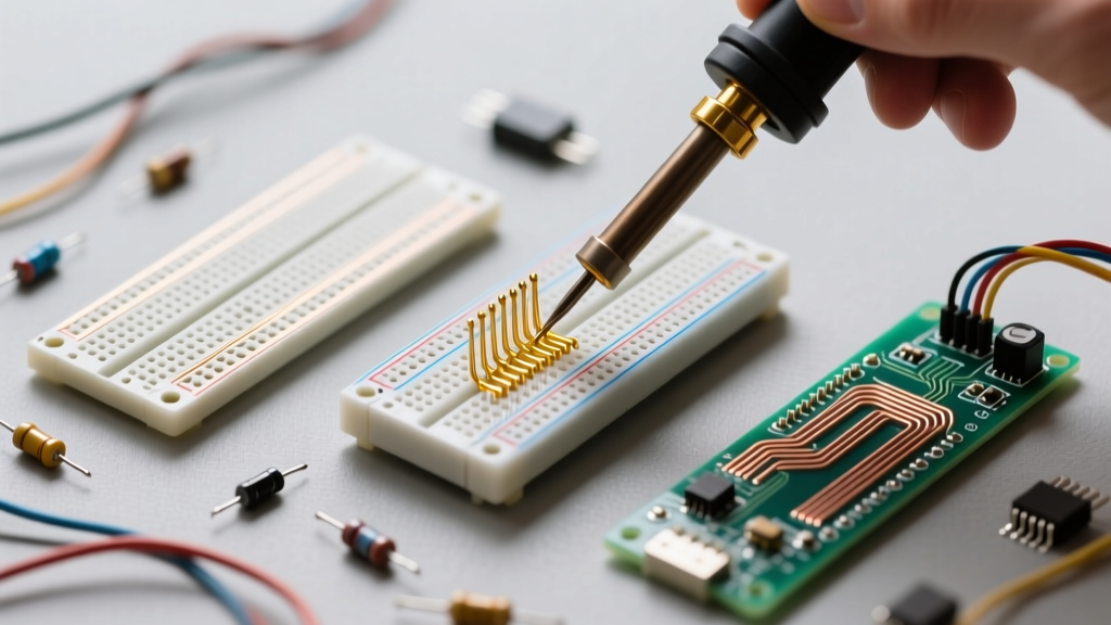
If you are searching for information on 'soldering breadboard' prototyping, you have likely encountered a common electronics terminology paradox. Standard solderless breadboards are constructed from ABS plastic and utilize internal phosphor bronze leaf-spring clips. The melting point of ABS plastic is approximately 105°C (221°F), while a standard soldering iron operates between 300°C and 380°C. Attempting to solder directly to a solderless breadboard will melt the plastic housing, destroy the internal contacts, and potentially release toxic fumes.
When engineers and makers refer to a 'soldering breadboard,' they are actually referring to solderable protoboards—commonly known as perfboard, stripboard (Veroboard), or busboard. These boards mimic the 0.1-inch (2.54mm) grid layout of a solderless breadboard but are constructed from high-temperature laminates with copper pads, allowing for permanent, reliable soldered connections. This quick-reference guide will break down the exact specifications, materials, and use cases for these permanent prototyping solutions.
Quick-Reference Matrix: Types of Solderable Protoboards
Choosing the right board topology dictates your routing strategy and the amount of physical labor required to complete your circuit. Below is a comparative matrix of the three primary solderable breadboard formats.
| Board Type | Copper Layout | Best Application | Trace Cutting Required? | Avg. Cost (10x15cm) |
|---|---|---|---|---|
| Perfboard | Isolated circular pads around each hole | Simple DIP logic, discrete components, custom routing | No (requires wire jumps) | $2.00 - $4.00 |
| Stripboard | Continuous parallel copper strips | Dense DIP ICs, op-amp circuits, audio filters | Yes (using a stripboard cutter) | $3.00 - $5.00 |
| Busboard | Interleaved power/ground buses with isolated pads | Microcontrollers, mixed-signal, high-power routing | No (built-in power rails) | $6.00 - $10.00 |
For a deeper dive into the historical and practical differences between these layouts, the Electronics Notes guide on stripboard and perfboard provides excellent foundational context.
Material Science: FR-4 vs. Phenolic Substrates
Not all solderable breadboards are created equal. The base substrate material determines the board's mechanical strength, thermal resistance, and longevity. When buying protoboards, you will encounter two primary materials:
1. Phenolic (Paper-Based)
Phenolic boards are made from kraft paper impregnated with phenolic resin. They are inexpensive, lightweight, and incredibly easy to cut or snap to size using a scoring knife. However, they have a low Glass Transition Temperature (Tg). If you dwell with a soldering iron for more than 3-4 seconds, the copper pads will easily lift off the substrate, and the board may char or emit a harsh burning odor. Phenolic is best reserved for quick, low-stakes hobby projects or simple through-hole LED circuits.
2. FR-4 (Fiberglass Epoxy)
FR-4 is the industry standard for professional printed circuit boards (PCBs) and high-quality protoboards. It consists of woven fiberglass cloth with an epoxy resin binder. FR-4 boasts a high Tg (typically 130°C to 170°C), meaning it can withstand repeated soldering and desoldering cycles without pad delamination. It is highly rigid and flame-retardant. The trade-off is that FR-4 cannot be snapped by hand; it requires a specialized carbide scoring tool or a jeweler's saw to cut, and drilling new mounting holes requires HSS or carbide bits to avoid fraying the fiberglass.
Plating Finishes: HASL vs. ENIG
The copper pads on a soldering breadboard must be treated to prevent oxidation. The two most common finishes you will encounter when purchasing protoboards are:
- HASL (Hot Air Solder Leveling): The board is dipped in molten lead-free tin and blown flat with hot air. HASL is highly affordable and provides excellent wetting for through-hole components. However, the surface is slightly uneven, making it less ideal for fine-pitch Surface Mount Devices (SMDs).
- ENIG (Electroless Nickel Immersion Gold): A thin layer of gold is deposited over a nickel barrier. ENIG provides a perfectly flat, highly oxidation-resistant surface. If your prototyping involves soldering SOIC, QFP, or 0805/0603 SMD components directly to the pads of your perfboard, ENIG is an absolute requirement for reliable solder joints.
Fast-Track Decision Tree: Which Board Do You Need?
Use this quick-reference decision framework to select the optimal soldering breadboard for your specific project constraints:
- Scenario A: You are building a simple 555 Timer or discrete transistor oscillator.
Recommendation: Standard FR-4 Perfboard. The isolated pads allow for flexible point-to-point wiring without worrying about cutting traces. - Scenario B: You are prototyping an audio pedal or a circuit with multiple 14-pin/16-pin DIP Op-Amps.
Recommendation: Stripboard (Veroboard). The continuous copper strips act as built-in bus lines for VCC and GND, drastically reducing the amount of jumper wire needed. - Scenario C: You are transitioning an Arduino or ESP32 from a solderless breadboard to a permanent shield.
Recommendation: Busboard Prototyping Board. The pre-routed, interleaved power and ground buses mimic the power rails of your solderless breadboard, ensuring clean power delivery to high-pin-count microcontrollers.
Essential Consumables for Protoboard Routing
Successful soldering on a protoboard requires specific wire gauges and insulation types. Standard PVC hook-up wire is often too bulky and its insulation will melt and shrink back when touched by a soldering iron. For professional-grade protoboard routing, utilize the following:
- 30 AWG Kynar Wire (Wire Wrap Wire): Kynar (PVDF) insulation has a very high melting point. It will not shrink back when soldered, allowing you to route dense, point-to-point jumper wires directly across the surface of the perfboard without fear of short circuits.
- 24 AWG Tinned Copper Bus Wire: Bare, tinned copper wire is essential for creating low-resistance ground planes and power buses across the underside of a perfboard. Because it is pre-tinned, it solders instantly to the copper pads.
- No-Clean Flux Pen: Protoboards lack the pre-applied flux found in PCB manufacturing. Applying a no-clean flux (such as Amtech or MG Chemicals) to your wire jumps before soldering ensures proper wetting and prevents cold joints. For more on flux chemistry, refer to the Adafruit Guide to Excellent Soldering.
Troubleshooting Common Protoboard Failures
When transitioning from a solderless breadboard to a soldered prototype, specific failure modes frequently arise. Use this troubleshooting table to diagnose and fix common issues.
| Failure Mode | Visual Symptom | Root Cause | Quick Fix / Prevention |
|---|---|---|---|
| Lifted Pads | Copper ring detaches from the fiberglass/paper substrate. | Excessive iron dwell time (>4 seconds) or using a Phenolic board with high heat. | Use FR-4 boards. Keep iron at 320°C. If a pad lifts, scrape the trace to the next via and solder a jumper wire. |
| Cold Joints | Dull, gray, or lumpy solder bead; poor electrical continuity. | Insufficient heat transfer; lack of flux; moving the wire before solder solidifies. | Apply liquid flux. Heat the pad and wire simultaneously for 2 seconds before feeding solder. |
| Accidental Bridges | Solder spans across two adjacent isolated pads, causing a short. | Using too much solder on 2.54mm pitch pads; dull iron tip. | Clean tip with brass wool. Use solder wick (desoldering braid) to remove excess solder and re-apply flux. |
| Thermal Relief Fractures | Intermittent connection that fails when the board is flexed. | Wire strain on the solder joint; lack of mechanical support for heavy components. | Apply a dab of RTV silicone or hot glue over heavy components (like electrolytic capacitors) to anchor them to the board. |
Final Prototyping Workflow Checklist
Before you power up your newly soldered breadboard prototype, run through this rapid verification checklist to prevent catastrophic component failure:
- Visual Inspection: Examine the underside of the board under a magnifying lamp or macro lens. Look for stray wire clippings (whiskers) bridging adjacent traces.
- Continuity Test: Use a digital multimeter in continuity mode to verify that VCC and GND rails are not shorted before applying power.
- Clean the Flux: Even 'no-clean' flux can become slightly conductive in high-humidity environments or high-impedance analog circuits. Clean the board with 99% Isopropyl Alcohol (IPA) and a stiff ESD-safe brush.
Mastering the soldering breadboard transition is a rite of passage in electronics design. By selecting the correct substrate (FR-4), utilizing high-temperature Kynar wiring, and understanding the topology of perfboard versus stripboard, you will create robust, permanent prototypes that survive the rigors of real-world testing. For further reading on fundamental soldering techniques, the SparkFun Soldering Fundamentals tutorial is an invaluable companion resource.