
The Evolution of Reflow Process Soldering in 2026 SMT Lines
In modern Surface Mount Technology (SMT) manufacturing, the reflow process soldering stage is the ultimate quality gate. As component miniaturization pushes into 01005 and 008004 metric packages, and high-density BGAs become standard in automotive and aerospace PCBs, the margin for thermal error has effectively vanished. In 2026, industrial reflow is no longer just about melting solder; it is a highly orchestrated thermal science governed by strict IPC/JEDEC J-STD-020 compliance and advanced fluid dynamics inside the oven chamber.
For production managers and process engineers, selecting the right reflow equipment and dialing in the exact thermal profile dictates yield rates, throughput, and long-term field reliability. According to reliability data published by NASA's Electronic Parts and Packaging (NEPP) program, improper thermal profiling remains a leading cause of latent solder joint fatigue in high-reliability electronics. This guide breaks down the current industrial landscape, comparing oven technologies, engineering the perfect thermal curve, and solving complex 2026 defect modes.
Industrial Reflow Oven Technologies: Convection vs. Vapor Phase
The industrial market is currently dominated by two primary reflow technologies. While forced convection holds the lion's share of high-volume SMT lines, vapor phase technology has seen a massive resurgence for specialized, high-thermal-mass applications.
Forced Convection Reflow (The High-Volume Standard)
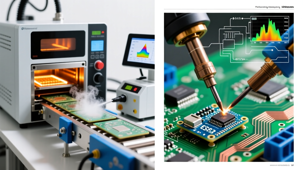
Convection ovens use a series of heated zones with forced air or nitrogen circulation to transfer heat to the PCB. Modern 2026 models, such as the BTU Pyramax 150N or the Heller 1913, feature advanced closed-loop convection controls that allow engineers to adjust gas flow rates independently of temperature. This prevents the 'blowing away' of solder paste on ultra-light micro-components while ensuring sufficient heat transfer to large ground planes.
- Pros: High throughput (up to 2.0 m/min conveyor speeds), seamless inline integration, lower initial capital cost for standard models.
- Cons: High power consumption, requires complex profiling to manage delta-T (temperature differences) across varied component masses.
Vapor Phase Soldering (The High-Reliability Specialist)
Vapor phase reflow utilizes an inert heat transfer fluid (like Galden) that boils to create a saturated vapor blanket. When the PCB enters the vapor zone, condensation occurs on the board, transferring heat uniformly regardless of the component's geometry or mass. Systems like the Asscon VP-Series or IBL VPC-600 are the gold standard for heavy copper power electronics and aerospace assemblies.
- Pros: Perfectly uniform heating (delta-T near zero), oxygen-free environment by default, lower peak temperatures required.
- Cons: Slower cycle times, fluid costs, risk of component shifting if vapor condensation is too aggressive.
Engineering the Perfect Thermal Profile for SAC305
The transition to lead-free alloys is complete in most sectors, with SAC305 (Sn96.5/Ag3.0/Cu0.5) remaining the industry workhorse. Engineering a Ramp-Soak-Spike (RSS) profile for SAC305 requires precise control over four distinct stages. The Surface Mount Technology Association (SMTA) regularly publishes technical papers emphasizing that flux chemistry must perfectly align with these thermal stages.
1. The Ramp Stage (Preheat)
Target: 1.0°C to 2.0°C per second.
The goal is to evaporate solvents in the solder paste without causing solder spattering or thermal shock to ceramic capacitors. In 2026, with the prevalence of Type 5 and Type 6 pastes for micro-BGAs, a controlled ramp of 1.5°C/s is optimal to prevent the 'hot plate' effect where the paste crusts over before internal solvents escape.
2. The Soak Stage (Flux Activation)
Target: 150°C to 190°C for 60 to 90 seconds.
This plateau allows the entire PCB assembly to reach thermal equilibrium. More importantly, it activates the rosin or synthetic resins in the flux, stripping oxidation from the copper pads and component leads. A soak time that is too short results in poor wetting; a soak that is too long depletes the flux's activators, leading to secondary oxidation before reflow even occurs.
3. The Reflow Stage (Time Above Liquidus - TAL)
Target: Peak 240°C to 250°C; TAL (above 217°C) for 45 to 75 seconds.
The solder powder melts, coalesces, and forms the intermetallic compound (IMC) layer. Keeping the TAL under 75 seconds is critical; excessive time in the liquid state causes excessive copper dissolution and thick, brittle IMC layers that fail under mechanical shock.
4. The Cooling Stage
Target: -2.0°C to -4.0°C per second.
Rapid cooling promotes a fine-grain microstructure in the solder joint, which significantly increases tensile strength and fatigue resistance. Modern inline ovens utilize dedicated water-chilled cooling zones to achieve this precise gradient without warping the FR4 substrate.
Industry Standard Note: All thermal profiles must be validated against IPC/JEDEC J-STD-020 moisture sensitivity and reflow standards. Component manufacturers specify absolute maximum peak temperatures (usually 260°C for large packages) that must never be exceeded, even for a single second, to prevent internal silicon delamination.
Nitrogen Inerting and Vacuum Modules: The 2026 ROI
Injecting nitrogen into a convection reflow oven to achieve an oxygen level below 1,000 ppm (and often below 250 ppm in premium setups) is no longer optional for high-reliability SMT lines. Nitrogen prevents secondary oxidation during the soak phase, drastically improving wetting and reducing solder ball defects.
Furthermore, the integration of Vacuum Reflow Modules (such as those found in the Heller 1809EXL vacuum series) has become a critical investment for automotive and EV battery management systems. By pulling a vacuum (down to 10-20 mbar) while the solder is in its liquid state, trapped flux outgassing is physically extracted from the joint. This reduces X-ray visible voiding in large thermal pads from a typical 15-20% down to less than 3%, vastly improving thermal conductivity and power dissipation.
2026 Buyer’s Matrix: Top Industrial Reflow Systems
| Equipment Model | Technology | Heated Zones | Est. Base Price (2026) | Best Industry Application |
|---|---|---|---|---|
| BTU Pyramax 150N | Convection (N2) | 10 Top / 10 Bot | $65,000 - $75,000 | High-mix consumer & telecom SMT |
| Heller 1913 Mark 5 | Convection (Air/N2) | 13 Top / 13 Bot | $80,000 - $95,000 | High-volume automotive & IoT |
| Asscon VP 800 | Vapor Phase | Vapor Blanket | $55,000 - $65,000 | Heavy copper, aerospace, power |
| Rehm VisionXP+ | Convection (N2) | 12 Top / 12 Bot | $70,000 - $85,000 | Medical devices, fine-pitch BGA |
| Heller 1809EXL (Vac) | Convection + Vacuum | 9 Zones + Vac | $120,000 - $145,000 | EV power modules, IGBT soldering |
Note: Pricing reflects base equipment costs and excludes installation, nitrogen generators, exhaust scrubbers, and extended warranty packages.
Preventing Complex Industrial Reflow Defects
Even with premium equipment, process drift can cause catastrophic yield loss. Here is how to troubleshoot the most expensive defects seen on 2026 SMT floors:
Head-in-Pillow (HiP) on Micro-BGAs
The Failure: The solder paste on the PCB pad melts, but the solder sphere on the BGA component does not fully collapse into it, leaving a non-continuous, hidden joint that fails under thermal cycling.
The 2026 Fix: HiP is primarily caused by substrate warpage during the reflow stage. Switch to a Type 5 or Type 6 solder paste with a highly active, halogen-free flux chemistry. Adjust the thermal profile to include a slightly longer soak time (up to 100 seconds) to ensure the BGA package and the PCB reach thermal equilibrium simultaneously, reducing the delta-T that causes warpage.
Tombstoning on 01005 Passives
The Failure: One end of a micro-capacitor or resistor lifts off the pad, standing upright like a tombstone.
The 2026 Fix: This is a classic wetting imbalance caused by uneven heating. If one pad is connected to a large copper pour (acting as a heat sink) and the other to a thin trace, the trace-side pad reaches reflow temperature first. The surface tension of the molten solder pulls the component upright. Solution: Implement thermal relief spokes on all ground-plane connections for micro-passives during the PCB CAD layout phase, and reduce the ramp rate in zones 1 and 2 to 1.0°C/s.
Excessive Solder Balling and Splatter
The Failure: Tiny spheres of solder form around the main joint or scatter across the PCB, risking short circuits in high-density areas.
The 2026 Fix: Solder balling indicates that moisture or aggressive solvents in the paste are boiling too rapidly. Verify your paste storage protocols (paste must be brought to room temperature for at least 4 hours before opening to prevent condensation). If storage is correct, increase the preheat ramp time to allow solvents to evaporate gently before the flux activates.
Final Thoughts on SMT Line Integration
Optimizing the reflow process soldering stage requires a holistic view of the SMT line. The oven is only as good as the stencil printing and pick-and-place accuracy that precedes it. In 2026, the most successful manufacturers are integrating closed-loop SPI (Solder Paste Inspection) data directly into the reflow oven's recipe management software, allowing for real-time thermal adjustments based on paste volume variations. By investing in the right thermal technology and strictly adhering to profile engineering, facilities can achieve first-pass yields exceeding 99.5%, even on the most complex, high-density assemblies.