
The Metallurgical Challenge: Why Ball Valves Fail During Soldering
Soldering a ball valve is widely considered one of the most unforgiving tasks in copper plumbing and HVAC/refrigeration DIY. Unlike standard copper couplings or elbows, a ball valve contains internal PTFE (polytetrafluoroethylene) or EPDM seats that allow the brass ball to rotate smoothly. The critical problem is thermal: PTFE begins to degrade and deform at approximately 500°F (260°C) and melts completely at 620°F (327°C). Meanwhile, standard lead-free plumbing solder flows between 430°F and 460°F.
Because the thermal conductivity of free-machining brass (Alloy C36000) is roughly 109 W/m·K, heat applied to the solder cup travels rapidly through the valve body. If the internal temperature exceeds the PTFE threshold before the solder ring fully capillarizes, the seals melt. Once the valve cools, the handle will either refuse to turn, or the valve will leak internally from the compromised seats. This guide details the precise thermal management techniques required to solder a ball valve flawlessly.
Essential Materials and Solder Selection for 2026
Choosing the correct solder alloy is your first line of defense. You need an alloy with a low melting point, high capillary action, and compliance with modern plumbing codes. As of 2026, silver-bearing lead-free alloys remain the gold standard for brass-to-copper transitions due to their superior tensile strength and vibration resistance.
| Solder Alloy | Composition | Melting Point (Flow) | Tensile Strength | Best Use Case | Est. 2026 Price (per lb) |
|---|---|---|---|---|---|
| Harris Stay-Brite 8 | 92% Tin, 8% Silver | 535°F (280°C) | 14,000 PSI | HVAC, refrigeration, high-vibration | $180 - $220 |
| Oatey Lead-Free Silver | 95% Tin, 5% Silver | 452°F (233°C) | 7,500 PSI | Potable water, standard brass valves | $90 - $110 |
| Standard 95/5 | 95% Tin, 5% Antimony | 452°F (233°C) | 6,000 PSI | General residential plumbing | $45 - $60 |
Note: Always verify that your solder meets the EPA's Reduction of Lead in Drinking Water Act requirements if the valve is on a potable water line. Never use 50/50 tin-lead solder on any modern water supply system.
Thermal Management: Heat Sinking Strategies
To protect the internal PTFE seals, you must actively pull heat away from the valve body while concentrating it on the solder cup. There are two primary methods used by master plumbers:
1. The Wet Rag Method (Traditional)
Wrap a 100% cotton rag soaked in ice water around the center of the valve body. Cotton holds water exceptionally well and will not melt. Never use synthetic blends (polyester/nylon), as the torch's radiant heat will melt the synthetic fibers directly onto the hot brass, creating a toxic mess and ruining the valve finish.
2. Heat Sink Paste (Modern & Superior)
For tight spaces where wrapping a rag is impossible, use a specialized heat-absorbing gel like RectorSeal Cold Gel. This water-based, non-toxic paste absorbs massive amounts of thermal energy as the water inside it undergoes phase change (evaporation). Apply a thick 1/4-inch layer over the valve body, avoiding the solder cups.
Pro-Tip: Always leave the ball valve in the OPEN position during soldering. A closed valve traps air and residual moisture inside the chamber. As the brass heats up, this trapped gas expands and will literally blow the molten solder out of the capillary joint, causing a guaranteed leak. Opening the valve also exposes the brass ball to the ambient air inside the pipe, helping it act as a secondary internal heat sink.
Step-by-Step Procedure: Soldering the Valve
Phase 1: Preparation and Fluxing
- Clean the Copper: Use 120-grit emery cloth to polish the outside of the copper pipe until it shines. Do not use steel wool, which leaves iron particles that cause galvanic corrosion.
- Clean the Valve Cups: Use a wire fitting brush sized exactly to your pipe diameter (e.g., 1/2" or 3/4") to clean the inside of the brass valve cups.
- Apply Flux: Apply a thin, even layer of water-flushable flux (like Oatey No. 95 or similar lead-free paste) to both the pipe and the inside of the valve cup. Too much flux will boil and create voids in the solder joint.
- Assemble and Wipe: Insert the pipe into the valve cup with a slight twisting motion to spread the flux. Wipe away any excess flux on the exterior with a dry rag.
Phase 2: The Heat Application
- Position the Heat Sink: Apply your wet cotton rags or heat sink gel to the center body of the valve.
- Select the Torch: For 1/2" and 3/4" valves, a standard Propane torch (approx. 3,600 BTU/hr) is preferred over MAP-Pro. MAP-Pro burns too hot (approx. 3,730°F flame temp) and can overheat a small brass valve in under 10 seconds. If you must use MAP-Pro, keep the flame constantly moving.
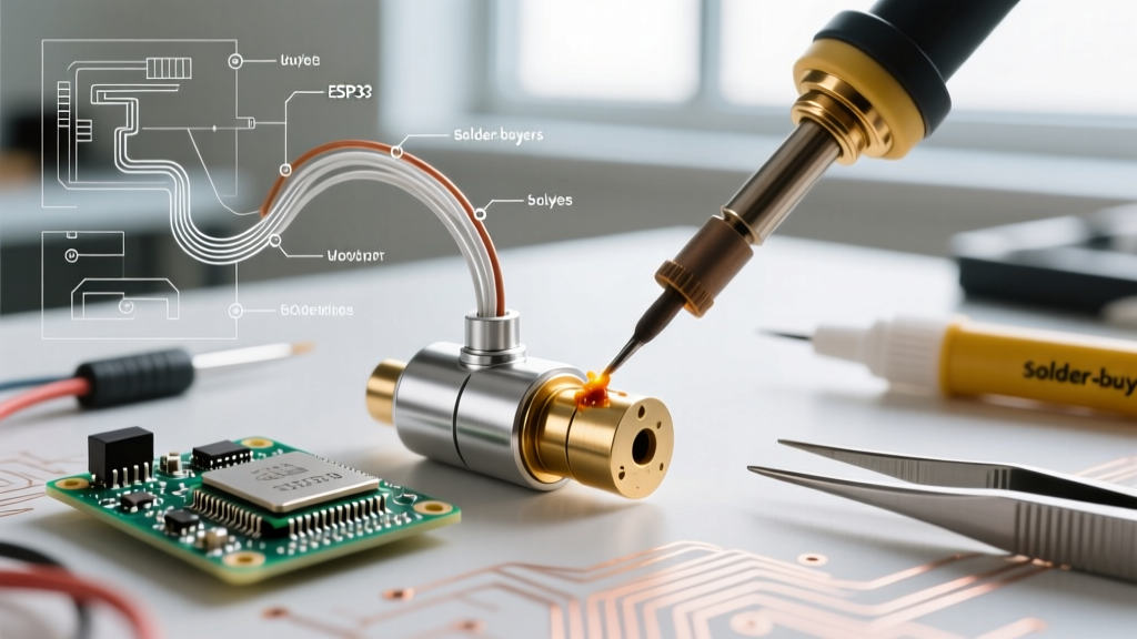
- Heat the Fitting, Not the Pipe: Apply the flame to the base of the valve cup, not the copper pipe. Brass requires more thermal energy to reach soldering temperature than thin-walled copper. Keep the flame moving in a circular pattern to distribute heat evenly.
- The Solder Test: After 8-12 seconds, remove the flame and touch the solder wire to the opposite side of the joint. If it doesn't melt instantly, apply heat for another 3 seconds. Do not melt the solder directly with the torch flame.
Phase 3: Capillary Drawing and Cooling
- Feed the Solder: Once the joint is at temperature, feed the solder wire into the gap. Capillary action will draw the molten metal deep into the cup. You should see a continuous silver ring form around the entire perimeter.
- Remove Heat Immediately: The moment the joint is full, pull the torch away. Overheating will burn the flux (turning it into a black, glassy carbon residue) and destroy the capillary seal.
- Wipe and Cool: Wipe the joint with a damp rag to smooth the solder bead and remove corrosive flux residue. Allow the valve to cool naturally. Do not quench it with cold water, as thermal shock can crack the brass casting or warp the internal ball.
Troubleshooting Common Failure Modes
Failure Mode 1: Solder Refuses to Draw Into the Joint
Cause: The flux has burned off due to excessive heat, or the copper was not cleaned properly, leaving copper oxide on the surface.
Solution: Allow the joint to cool completely. Disassemble the joint using a solder sucker or heat gun. Re-clean the copper and brass with emery cloth, re-apply fresh flux, and try again with a lower BTU torch or faster heating technique.
Failure Mode 2: Pinhole Leaks After Pressurization
Cause: Microscopic water droplets inside the pipe turned to steam during heating, blowing microscopic holes in the molten solder before it solidified.
Solution: Use the 'White Bread Trick'. Stuff a ball of plain white bread (no crusts) into the pipe upstream of the valve to act as a temporary water dam. Dry the pipe completely with compressed air or a shop vac, solder the joint, and then turn the water on. The water pressure will dissolve the bread and flush it out through the nearest faucet aerator.
Failure Mode 3: Valve Handle is Stiff or Locked After Cooling
Cause: The internal PTFE seats melted and fused to the brass ball due to prolonged heat exposure or lack of a heat sink.
Solution: Unfortunately, there is no fix for this. The valve must be cut out with a tubing cutter and replaced. To prevent this, strictly adhere to the heat-sinking protocols and use the lowest effective BTU torch for your pipe diameter.
Final Considerations for Electronics and HVAC Cooling Loops
While often associated with residential plumbing, soldering ball valves is a critical skill in custom PC liquid cooling loops, industrial electronics water-cooling, and HVAC refrigeration lines. In these applications, a leaking valve can destroy thousands of dollars in sensitive microcontrollers, server racks, or PCB assemblies. When working on electronics cooling loops, always pressure-test the soldered ball valve assembly with dry nitrogen at 150 PSI for 24 hours before introducing any dielectric fluids or water into the system. This ensures the capillary joints are structurally sound and protects your valuable electronic infrastructure.