
The Shift to Automated PCB Assembly in 2026
As the electronics manufacturing sector navigates persistent skilled labor shortages and increasingly stringent reliability requirements, the soldering automation machine has transitioned from a luxury for high-volume fabs to a necessity for mid-sized and boutique PCB assembly houses. In 2026, achieving IPC-A-610 Class 3 compliance consistently across high-mixed, low-to-medium volume production runs requires moving beyond manual hand soldering. This comprehensive guide dissects the technical specifications, total cost of ownership (TCO), and critical setup parameters for modern automated soldering platforms.
Core Architectures: Robotic vs. Selective Soldering
Choosing the right automation architecture depends entirely on your board density, component mix, and thermal mass requirements. Below is a technical breakdown of the two dominant automated through-hole and mixed-technology soldering methods.
1. Robotic Soldering Systems (Point-to-Point)
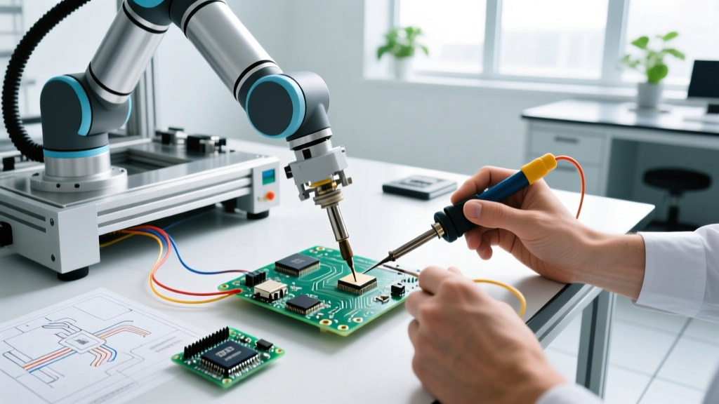
Robotic soldering machines utilize multi-axis Cartesian or SCARA arms equipped with integrated soldering irons and automated wire feeders. Systems like the Hakko FR-8000 series or the JBC ALE-250 robotic platform excel in high-mixed environments where selective wave soldering is impractical due to nearby heat-sensitive SMD components.
- Best For: High-mix/low-volume boards, odd-form components, and heat-sensitive mixed-technology PCBs.
- Pricing (2026): $8,000 to $18,000 per cell, depending on vision systems and axis complexity.
- Key Advantage: Pinpoint thermal control. Advanced stations use active tip temperature compensation, recovering to 350°C within 0.5 seconds of joint contact.
2. Selective Soldering Machines (Mini-Wave)
Selective soldering machines, such as the ERSA VERSAFLOW 335 or Nordson ASYMTEK platforms, use a localized mini-wave of molten solder to process through-hole pins. They utilize drop-jet flux dispensers and programmable X-Y-Z gantries to move the board over the solder nozzle.
- Best For: Medium-to-high volume through-hole processing, heavy ground-plane boards, and multi-layer power electronics.
- Pricing (2026): $65,000 to $140,000+ depending on inline conveyor integration and dual-pot configurations.
- Key Advantage: Unmatched throughput for standard DIP components, processing hundreds of joints per minute with perfect barrel fill.
Total Cost of Ownership (TCO) & ROI Matrix
When justifying the capital expenditure of a soldering automation machine to stakeholders, you must calculate the TCO over a 36-month period. The table below compares a 3-operator manual line against a single robotic cell and a selective soldering line.
| Cost Factor (3-Year Projection) | Manual Line (3 Operators) | Robotic Cell (1 Unit) | Selective Solder Line |
|---|---|---|---|
| Capital Equipment Cost | $4,500 (Benches/Irons) | $14,000 | $95,000 |
| Labor Cost (Fully Burdened) | $450,000 | $150,000 (1 Supervisor) | $150,000 (1 Supervisor) |
| Consumables (Tips, Solder, Flux) | $18,000 | $12,500 | $28,000 (Bulk Solder/N2) |
| Rework & Scrap Rate (Est.) | 4.5% ($22,000) | 1.2% ($6,000) | 0.8% ($4,500) |
| Estimated 3-Year TCO | $494,500 | $182,500 | $277,500 |
Note: ROI for robotic cells in high-mix environments typically breaks even at 11-14 months, while selective lines require higher baseline volumes to justify the initial CAPEX.
Critical Setup Parameters for IPC Class 3 Compliance
According to Surface Mount Technology Association (SMTA) guidelines and IPC standards, automation does not guarantee quality; it only guarantees repeatability. If your baseline parameters are flawed, the machine will perfectly repeat defective solder joints. Below are the non-negotiable setup parameters for 2026 production environments.
Thermal Profiling and Preheat Ramps
Thermal shock is the primary killer of multi-layer ceramic capacitors (MLCCs) and via barrels in automated soldering. Whether using a robotic iron or a selective preheat array, the thermal profile must be strictly managed.
- Ramp Rate: Limit the temperature ramp to 1°C to 3°C per second. Robotic systems must utilize a "hover and preheat" dwell time of 1.5 to 2.0 seconds before solder wire feed initiation.
- Time Above Liquidus (TAL): For SAC305 lead-free alloys (melting point ~217°C), maintain the joint temperature above liquidus for exactly 45 to 90 seconds. Exceeding 120 seconds accelerates intermetallic compound (IMC) growth, leading to brittle joints.
- Top-Side Preheat: For selective soldering machines processing 4-layer+ boards with heavy copper (2oz+), top-side IR preheat must be engaged to bring the board surface to 130°C–150°C before the mini-wave contacts the bottom pins.
Flux Deposition and Nitrogen Inerting
Flux activation and oxidation prevention are where most automated setups fail.
- Robotic Wire Feed: Use solder wire with a 2.5% to 3.0% rosin-based (ROL0 or ROL1) flux core. Ensure the automated wire feeder encoder is calibrated to deliver exactly 12mm to 18mm of 0.8mm wire per standard 0805/1206 pad joint to prevent flux starvation.
- Selective Nitrogen (N2) Environment: Selective solder pots must be inerted with nitrogen. Maintain the oxygen level in the localized soldering environment below 1,000 ppm. This reduces dross generation by up to 85% and dramatically improves wetting on OSP (Organic Solderability Preservative) finishes.
Common Failure Modes & Machine Troubleshooting
Even with advanced vision systems and closed-loop thermal controls, specific failure modes plague automated soldering. Use this diagnostic matrix to adjust machine parameters on the fly.
1. Icicles and Solder Bridging
The Defect: Excess solder clings to the pin or bridges to adjacent pads, common in selective mini-wave processes.
Root Cause: The board is separating from the solder wave too quickly, or the solder temperature is too low, increasing surface tension.
Machine Adjustment: Program a "drag" or "dwell" exit move. Instruct the X-Y gantry to move the board 2mm in the direction of the wave flow at a slow speed (2mm/s) before lifting the Z-axis. Increase pot temperature by 5°C (max 265°C for SAC305).
2. Insufficient Barrel Fill (Selective) or Cold Joints (Robotic)
The Defect: Solder fails to wick to the top of the plated through-hole (PTH), violating IPC Class 3 requirements for 75% minimum barrel fill.
Root Cause: Inadequate thermal mass transfer. The flux has burned off before the solder flows, or the pin is acting as a heat sink.
Machine Adjustment: For selective machines, increase the top-side IR preheat dwell time by 15 seconds. For robotic systems, increase the iron tip contact area (switch from a conical tip to a chisel or bevel tip) and extend the initial dry-heat dwell time by 1.0 second before feeding the wire.
3. Tip Oxidation and Non-Wetting (Robotic Systems)
The Defect: The solder wire balls up and rolls off the robotic iron tip instead of transferring to the pad.
Root Cause: The automated tip cleaner is over-cycling, or the machine is leaving the iron at 380°C during idle periods.
Machine Adjustment: Program the machine's sleep mode to drop the tip temperature to 200°C after 120 seconds of inactivity. Adjust the automatic brass-wool tip cleaner to activate only once every 15 joints, not after every single cycle, to preserve the iron plating.
Final Verdict: Scaling Your Assembly Line
Investing in a soldering automation machine in 2026 is less about replacing human dexterity and more about enforcing process control. If your facility runs high-mix, low-volume prototypes with dense SMD clearances, a robotic soldering cell offers the fastest ROI and the lowest thermal risk. If you are processing high-volume power supplies, automotive ECUs, or telecom backplanes with heavy ground planes, a selective soldering machine with nitrogen inerting is mandatory for IPC Class 3 reliability. Evaluate your specific board profiles, calculate your true burdened labor costs, and select the architecture that aligns with your thermal mass requirements.