
The High-Stakes Reality of BGA Memory Rework
In the modern era of ultrabooks and ARM-based architecture, the era of slot-in SO-DIMM memory is largely over. For advanced technicians and ambitious DIYers, a soldered RAM upgrade—such as replacing 8GB LPDDR4X chips with 16GB or 32LPDDR5X equivalents on a logic board—represents the frontier of micro-soldering. However, executing a Ball Grid Array (BGA) rework on high-density memory modules is not merely a test of soldering skill; it is an exercise in rigorous environmental and safety management.
Unlike through-hole components or large QFP ICs, BGA memory chips sit on high-layer-count PCBs (often 8 to 12 layers) that act as massive heat sinks. Applying localized heat without strict safety protocols leads to catastrophic failure modes: PCB delamination, pad cratering, the 'popcorn effect' from trapped moisture, and severe electrostatic discharge (EOS) damage to the new silicon. This guide outlines the uncompromising safety best practices required to perform a soldered RAM upgrade in 2026, protecting both the technician and the multi-hundred-dollar donor components.
Moisture Sensitivity and the 'Popcorn Effect'
Before a heat gun ever powers on, moisture management is your first critical safety hurdle. LPDDR5 and LPDDR5X memory chips are highly moisture-sensitive, typically rated at MSL 3 or MSL 4 under IPC J-STD-033 standards. If a chip or a bare PCB absorbs ambient humidity, the rapid vaporization of water during the 245°C reflow phase will cause internal micro-fractures or violent delamination—a phenomenon known as the popcorn effect.
Mandatory Baking Protocols
- Donor Chips: Bake new BGA memory ICs in a specialized convection oven (not a food dehydrator) at 40°C for 96 hours, or 125°C for 24 hours prior to reballing.
- Host PCB: After desoldering the original RAM, the bare motherboard must be baked to drive out moisture introduced during the initial teardown and desoldering phases. Use a PCB preheater or industrial oven set to 100°C for a minimum of 4 hours.
- Storage: Post-bake, components must be stored in a nitrogen-purged dry cabinet maintaining less than 5% Relative Humidity (RH) until the exact moment of reflow.
Thermal Profiling: Preventing PCB Delamination
The most common cause of fatal board damage during a soldered RAM upgrade is thermal shock. Applying 350°C top-heat to a cold motherboard creates a massive temperature gradient (Delta-T). The fiberglass and copper layers expand at different rates, warping the board and tearing the micro-vias connecting the BGA pads to the inner layers.
To mitigate this, a bottom-side preheater is non-negotiable. Below is the industry-standard thermal profile for lead-free SAC305 solder reflow on high-mass logic boards.
| Profile Stage | Target Temperature | Duration | Purpose & Safety Note |
|---|---|---|---|
| Preheat (Bottom) | 120°C - 135°C | 3 - 5 mins | Reduces Delta-T. Use a Hakko FR-830 or equivalent IR preheater to warm the entire board evenly. |
| Soak (Top) | 170°C - 190°C | 60 - 90 secs | Activates the tacky flux (e.g., Amtech NC-559-V2-TF) and evaporates volatile solvents to prevent solder splatter. |
| Reflow (Top) | 235°C - 245°C | 30 - 45 secs | Liquefies the SAC305 solder spheres (melting point ~217°C). Monitor with a K-type thermocouple. |
| Cooling | Ambient (25°C) | Gradual | Do NOT use compressed air. Allow the board to cool naturally on the preheater to prevent thermal contraction cracking. |
Electrostatic Discharge (EOS/ESD) Mitigation
Modern LPDDR5X modules operate at extremely low voltages (often below 0.5V for core logic) and feature nanometer-scale gate oxides. An electrostatic discharge that you cannot even feel (under 3,000V) can instantly puncture the gate oxide of a memory controller or the RAM die itself, resulting in a silent, localized failure that manifests later as random kernel panics.
According to the ESD Association's ANSI/ESD S20.20 standards, a proper micro-soldering workbench must implement a grounded equipotential bonding system.
ESD Workbench Checklist
- Dissipative Mat: Use a dual-layer ESD mat with a surface resistance of 10^6 to 10^9 ohms. Connect it to the facility ground via a 1-megohm current-limiting resistor.
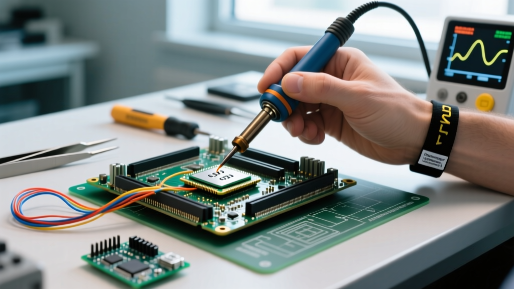
- Wrist Strap: Wear a continuous monitor wrist strap. The 1MΩ resistor protects the user from shock if they accidentally touch a live voltage rail while probing the board.
- Ionizer: BGA rework involves peeling Kapton tape and handling plastic BGA stencils, which generate massive triboelectric charges. An overhead bench ionizer is required to neutralize static on non-conductive surfaces.
- Tool Grounding: Ensure your soldering iron and hot air handpieces (e.g., Quick 861DW) feature grounded tips. Verify tip-to-ground resistance is less than 2 ohms using a multimeter.
Chemical Hazards and Fume Extraction
A successful soldered RAM upgrade requires copious amounts of high-activity flux to break the surface tension of the 0.35mm BGA solder spheres and ensure proper wetting. When heated, the rosin and synthetic resins in these fluxes vaporize, releasing colophony and aliphatic aldehydes.
Health Warning: Prolonged inhalation of rosin-based solder fumes is a known respiratory sensitizer and can lead to occupational asthma. According to the UK Health and Safety Executive (HSE), colophony fume exposure must be strictly controlled via localized exhaust ventilation (LEV) to prevent irreversible lung damage.
To protect your respiratory health during BGA rework:
- Capture Velocity: Position your fume extractor nozzle within 2 to 3 inches of the rework site. The capture velocity must exceed 100 feet per minute (FPM) to pull the buoyant thermal plume before it reaches your breathing zone.
- Filtration Stages: Standard HEPA filters only capture particulate matter (flux smoke). You must use a multi-stage filter featuring a minimum of 5 lbs of activated carbon to adsorb the harmful volatile organic compounds (VOCs) and aldehydes.
- Cleaning Solvents: Post-rework cleaning involves isopropyl alcohol (IPA) or specialized saponifiers. Use these only in well-ventilated areas and wear nitrile gloves, as flux residues combined with heat can cause contact dermatitis.
Step-by-Step Safety Execution for the Workbench
When you are ready to execute the soldered RAM upgrade, follow this sequential safety workflow to ensure maximum yield and personal protection:
- Prep & PPE: Don ESD-safe garments, safety glasses (to protect from microscopic solder splatter), and connect your wrist strap.
- Board Support: Secure the motherboard on a specialized BGA rework fixture. High-layer-count boards will sag when heated to 135°C; use adjustable brass standoffs beneath the CPU and RAM cutouts to support the PCB and prevent gravitational warping.
- Shielding: Apply high-temperature Kapton tape and aluminum foil tape to surround the BGA site. This protects adjacent SMD components (like decoupling capacitors and PMICs) from the hot air vortex.
- Thermocouple Placement: Attach a K-type thermocouple directly to the PCB substrate next to the RAM pads using high-temp tape. Never fly blind; rely on real-time telemetry, not just the digital readout on your hot air station.
- Execution: Follow the thermal profile table above. Once the solder liquefies, use vacuum tweezers to lift the IC. Do not pry with a spudger, as the pads are exceptionally fragile at reflow temperatures.
FAQ: Troubleshooting Safety and Yield Issues
Why did my PCB pads lift off during the desoldering phase?
Pad cratering or lifting is almost always a result of mechanical force applied before the solder reached a full liquidus state, or a massive Delta-T causing the board to warp. Ensure your bottom preheater has thoroughly soaked the board at 130°C, and verify that your hot air nozzle is providing even heat across the entire BGA footprint before attempting removal.
Is it safe to use a heat gun instead of a dedicated BGA rework station?
No. Consumer heat guns lack precise airflow control, thermal feedback, and localized nozzle profiling. A dedicated station like the JBC JTSE or Quick 861DW allows you to dial in exact CFM (cubic feet per minute) and temperature parameters. Uncontrolled airflow will blow away tiny 01005 decoupling capacitors surrounding the RAM chips, creating a secondary repair nightmare.
How do I verify the IPC standards for this type of repair?
Professional repair facilities adhere strictly to the IPC-7711/7721 standard for Rework, Modification, and Repair of Electronic Assemblies. This documentation provides exhaustive guidelines on BGA pad preparation, stencil alignment, and acceptable wetting angles for lead-free BGA spheres.
Performing a soldered RAM upgrade is a masterclass in thermal dynamics and material science. By respecting the strict safety protocols surrounding moisture, ESD, thermal profiling, and chemical exposure, you transition from a hobbyist with a hot air gun to a precision micro-soldering technician capable of reviving and upgrading modern, high-density logic boards.