
The Thermodynamics of SMT: Why a Decision Framework Matters
Designing a reliable reflow soldering profile is not a matter of simply loading a default oven recipe and hoping for the best. In 2026, with the proliferation of ultra-dense 01005 passives, high-I/O BGAs, and mixed-technology boards featuring heavy copper inner layers, thermal management requires a rigorous, physics-based decision framework. A poorly tuned profile leads to catastrophic yield losses, including head-in-pillow (HiP) defects, tombstoning, and brittle intermetallic compound (IMC) growth.
This guide provides a comprehensive decision framework for SMT process engineers and advanced DIY builders to select, tune, and troubleshoot the ideal reflow soldering profile based on specific assembly variables.
Phase 1: Assessing Assembly Variables (The Inputs)
Before touching the oven zones, you must quantify the thermal constraints of your specific PCB assembly (PCBA). The decision framework begins with three critical inputs:
1. Solder Paste Alloy and Liquidus Temperature
The alloy dictates your baseline thermal targets. While NASA workmanship standards and commercial IPC guidelines outline general tolerances, the specific alloy chemistry sets the hard limits:
- SAC305 (Sn96.5/Ag3.0/Cu0.5): The industry standard lead-free alloy. Liquidus is 217°C. Requires peak temperatures of 235°C–245°C.
- Sn63/Pb37: Traditional eutectic leaded solder. Liquidus is 183°C. Peak target is 215°C–225°C.
- Low-Temp Alloys (e.g., Sn42/Bi57/Ag1): Liquidus around 138°C. Ideal for heat-sensitive components and step-soldering processes, peaking at 165°C–175°C.
2. PCB Thermal Mass and Layer Count
A 2-layer FR4 board with 1 oz copper behaves entirely differently than a 12-layer impedance-controlled board with 4 oz copper ground planes. High-mass boards act as massive heat sinks, creating a severe Delta T (temperature difference) between the board's surface, internal layers, and component leads. High-mass boards mandate longer soak times to achieve thermal equilibrium.
3. Component Sensitivity and MSL Ratings
Always cross-reference your component datasheets against IPC J-STD-020 standards for Moisture Sensitivity Levels (MSL). Components rated MSL 3 or higher may require strict pre-baking to prevent the "popcorn effect" (internal delamination and cracking caused by rapid moisture expansion during the reflow spike).
Phase 2: Selecting the Profile Geometry
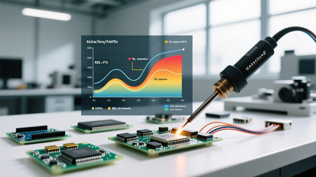
The two dominant profile geometries in modern SMT are Ramp-Soak-Spike (RSS) and Ramp-To-Spike (RTS). Choosing between them is the core of the reflow soldering profile decision framework.
| Profile Type | Thermal Geometry | Best Use Case | Pros & Cons |
|---|---|---|---|
| Ramp-Soak-Spike (RSS) | Linear ramp, extended flat soak plateau, sharp spike to peak, linear cool. | Complex boards, high Delta T, mixed SMT/TH components, heavy copper. | Pros: Excellent thermal equalization. Voids flux solvents safely. Cons: High energy use. Prolonged heat can oxidize pads and degrade sensitive ICs. |
| Ramp-To-Spike (RTS) | Continuous, steady ramp directly to peak temperature, followed by linear cool. | Simple boards, low Delta T, high-density micro-BGAs, lead-free SAC alloys. | Pros: Reduces oxidation, saves energy, minimizes IMC overgrowth. Cons: High risk of solder balling if solvent outgassing is too rapid. |
According to extensive metallurgical research shared on the Indium Corporation engineering blog, the RTS profile is increasingly preferred for modern SAC305 pastes because it minimizes the time the solder is exposed to high-temperature oxidation before liquefying, resulting in brighter, more reliable joints.
Phase 3: Dialing in the Four Critical Zones
Once the geometry is selected, apply these specific parameter guardrails to your oven zones. These metrics assume a standard SAC305 paste on a medium-complexity board.
- Preheat / Ramp Zone: Target a ramp rate of 1.5°C/s to 2.5°C/s. Failure Mode: Ramping faster than 3°C/s causes rapid solvent boiling in the paste flux, leading to solder spatter and micro-balling around fine-pitch QFNs.
- Reflow / Liquidus Zone (TAL): Target a peak of 235°C to 245°C. The Time Above Liquidus (TAL) must be strictly between 45 and 75 seconds.
- Cooling Zone: Target a controlled cooling rate of 2.0°C/s to 4.0°C/s down to 150°C. Failure Mode: Cooling too slowly results in a coarse, grainy solder joint structure prone to fatigue. Cooling too fast (>5°C/s) risks thermal shock, cracking multi-layer ceramic capacitors (MLCCs).
Engineering Pro-Tip: Never rely solely on the oven's built-in thermocouples. The oven measures ambient air temperature, not the actual PCBA. You must use a dedicated thermal profiler (e.g., KIC X5 or Datapaq Q18) with thermocouples physically attached to the board using high-temperature epoxy (like Loctite EA 934NA) or Kapton tape. Place one TC on a massive ground plane, one on the largest IC body, and one on a small 0402 passive to measure true Delta T.
Phase 4: Troubleshooting Edge Cases & Failure Modes
Even with a mathematically sound profile, edge cases occur. Use this troubleshooting matrix to adjust your reflow soldering profile based on post-reflow X-ray and AOI (Automated Optical Inspection) results.
Defect: Head-in-Pillow (HiP) in BGAs
The Physics: The BGA sphere melts, but the paste on the PCB pad does not fully liquefy or wet, leaving a non-metallic gap resembling a head resting on a pillow. The Fix: This is almost always a thermal deficit or PCB warpage issue. Increase your peak temperature by 5°C or extend the TAL by 10 seconds. If the board is bowing during reflow, implement a physical support tooling jig in the oven conveyor to prevent Z-axis warpage.
Defect: Tombstoning on 0402 / 0201 Passives
The Physics: One pad of the passive component reaches reflow temperature before the other. The surface tension of the liquefied solder on the hotter pad pulls the component upright. The Fix: Your Delta T is too high. Extend the soak zone by 30 seconds to ensure both pads reach thermal equilibrium before the spike. Verify your PCB footprint design; asymmetric trace widths connected to the pads will cause uneven heat sinking.
Defect: Excessive Voiding in QFN Ground Pads
The Physics: Flux gases are trapped beneath the component as the solder melts around the edges first, sealing the escape route. The Fix: Modify your stencil design to use a window-pane (cross-hatch) aperture pattern for the ground pad, reducing paste volume and creating gas escape channels. Alternatively, increase the ramp rate slightly to accelerate solvent burn-off before the perimeter seals.
Essential Profiling Tools for 2026
To execute this framework, you need precision hardware. For high-volume SMT lines, the KIC X5 and BTU Pyramax ovens with closed-loop profiling remain the gold standard, automatically adjusting zone setpoints in real-time based on the passing board's thermal mass. For prototyping labs and advanced DIY setups, benchtop reflow ovens like the LPKF ProtoFlow S4 or modified toaster ovens paired with a standalone TC Labs thermocouple data logger (approx. $350–$500) provide the necessary data to map your profile accurately.
Final Thoughts on the Decision Framework
Mastering the reflow soldering profile requires shifting from a trial-and-error mindset to a deterministic engineering approach. By systematically evaluating your alloy chemistry, mapping your board's thermal mass, selecting the appropriate RSS or RTS geometry, and strictly controlling your TAL and cooling rates, you will consistently achieve IPC-A-610 Class 2 and Class 3 compliant solder joints. Document every profile change, maintain your thermocouples, and let the thermal data drive your SMT yield.