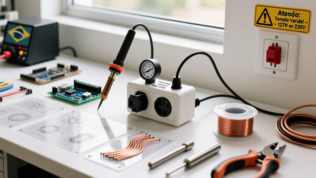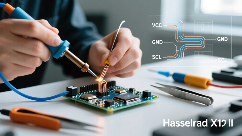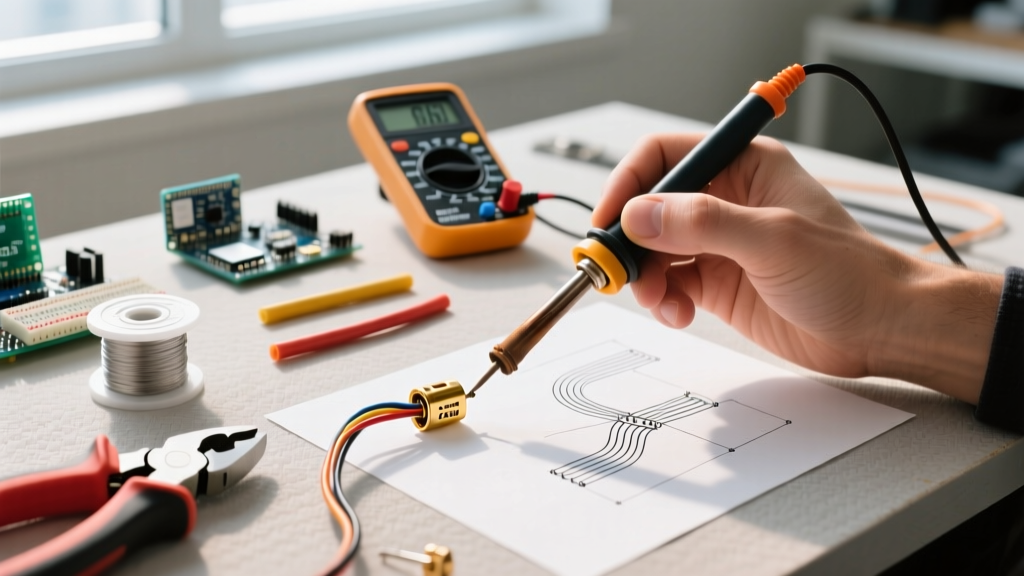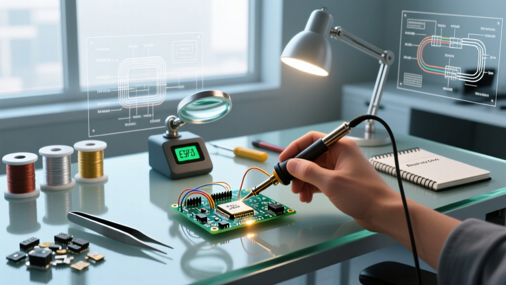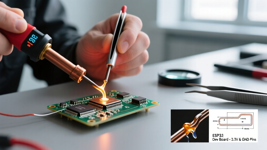

If you have ever searched for electronics tutorials online, you have likely encountered the infamous phenomenon of stock photo soldering. These are the viral, often hilarious images used by media outlets and generic blogs that depict people holding soldering irons by the hot ceramic shaft, attempting to solder insulated wires without stripping them, or creating massive, dull, mountainous blobs of solder on a printed circuit board (PCB). While these images make for great internet memes, they perpetuate dangerous habits and fundamental misunderstandings of metallurgy and thermal dynamics.
As a beginner or intermediate DIYer, learning to differentiate between media myths and actual professional techniques is critical. In this method comparison, we will dissect the most common 'stock photo soldering' fails and contrast them directly with real-world, IPC-compliant soldering methods used by aerospace engineers and professional PCB assemblers.
The Anatomy of a Stock Photo Soldering Fail
Stock photography models are rarely electronics technicians. They are actors handed a prop and told to 'look busy.' This results in three primary methodological failures that violate basic thermodynamics and safety standards.
1. The 'Solder the Solder' Technique
In countless stock images, the model touches the soldering iron tip directly to the spool of solder wire, melting it into a puddle, and then attempts to 'paint' the liquid solder onto a cold copper pad. This is a fundamental violation of thermal transfer principles. Solder is not glue; it is a metallurgical alloy that must wet to the base metals. If the copper pad and the component lead are not heated above the solder's liquidus temperature, the solder will simply ball up and sit on top of the surface tension, creating a catastrophic 'cold joint' that will fail under the slightest mechanical vibration.
2. The Dagger Grip and Safety Violations
Media depictions frequently show users gripping the soldering iron handle like a kitchen knife or a dagger. This grip eliminates all fine motor control, making it impossible to stabilize the tip on a 0.1-inch (2.54mm) through-hole pad. Furthermore, stock photos routinely omit personal protective equipment (PPE). Models are often shown leaning directly over the PCB, inhaling colophony and flux fumes without any localized exhaust ventilation.
3. The Missing Flux Phenomenon
Real-world soldering relies heavily on chemical flux to remove metal oxides. Stock photo soldering almost exclusively features 'dry' soldering with heavily oxidized, blackened iron tips. Without flux, the solder refuses to flow, leading users to apply excessive heat for prolonged periods, which inevitably delaminates the copper traces from the fiberglass PCB substrate.
Real-World Soldering: IPC-A-610 Compliant Methods
Professional electronics manufacturing is governed by strict visual and mechanical standards, most notably the IPC-A-610 Standard for the Acceptability of Electronic Assemblies. Let us compare the professional method against the media myth.
The Professional Thermal Transfer Sequence
Instead of melting solder on the iron and transferring it, a professional uses the soldering iron as a thermal bridge. The correct method follows a precise, timed sequence:
- Positioning: Hold the iron using a relaxed 'pencil grip' to maximize wrist stability and fine motor control.
- Simultaneous Contact: Touch the chisel or bevel tip of the iron so that it contacts both the component lead and the copper PCB pad simultaneously.
- The 2-Second Rule: Allow the thermal mass of the joint to absorb heat for 1 to 2 seconds.
- Feed the Solder: Introduce the solder wire to the joint, not the iron tip. The heat from the pad and lead will melt the solder, allowing capillary action to pull it through the plated through-hole (PTH).
- Withdrawal: Remove the solder wire first, then immediately remove the iron, allowing the joint to cool naturally without blowing on it.
Expert Insight: According to high-reliability aerospace guidelines like NASA-STD-8739.3, a proper solder joint must exhibit a smooth, shiny, concave fillet with a wetting angle of less than 90 degrees. Dull, convex, or grainy joints are immediate grounds for rejection.
Side-by-Side Method Comparison Matrix
The following table breaks down the exact technical differences between the methods depicted in generic media and the methods required for reliable electronics assembly.
| Technique Variable | Stock Photo Depiction (Media Myth) | IPC-Compliant Reality (Professional) | Consequence of Media Method |
|---|---|---|---|
| Heat Application | Iron melts solder wire directly; solder is 'painted' on. | Iron heats pad and lead; solder is fed into the joint. | Cold joints, insufficient wetting, high electrical resistance. |
| Grip Style | 'Dagger' or fist grip. | Relaxed pencil grip. | Hand fatigue, accidental burns, damaged nearby components. |
| Flux Usage | None visible; dry ironing with oxidized tips. | Rosin-core wire or external No-Clean liquid flux. | Oxidation, solder bridging, non-wetting, charred PCBs. |
| Tip Geometry | Long, needle-like conical tips. | Chisel, bevel, or hoof tips matched to pad size. | Poor thermal mass transfer; conical tips lack surface area. |
| Solder Alloy | Unknown, often thick plumbing solder. | Sn63/Pb37 (Eutectic) or SAC305 (Lead-Free). | Acid-core plumbing solder destroys copper traces. |
Equipment Realities: Props vs. PID-Controlled Stations
One of the most damaging aspects of stock photo soldering is the equipment shown. Media images frequently feature cheap, unregulated $10 plug-in irons that lack thermal feedback. In reality, modern soldering relies on Proportional-Integral-Derivative (PID) temperature control to maintain consistent thermal output.
The Problem with Unregulated Irons
Cheap irons operate on a simple resistive heating element. When they touch a large ground plane on a PCB, the copper acts as a massive heat sink, rapidly dropping the tip temperature. Because the iron lacks a thermal sensor, it cannot compensate, resulting in a stalled, cold joint. Conversely, when left in the stand, these irons can spike to over 450°C (842°F), rapidly oxidizing the tip and destroying the flux chemistry.
What Professionals Actually Buy in 2026
If you are building a kit based on real-world requirements, you should look for stations or smart irons that feature active thermal recovery:
- Hakko FX-888D: The industry-standard benchtop station. It uses a T18 ceramic heating element with a built-in thermocouple, recovering from thermal drops in milliseconds. Typically priced around $115.
- Pinecil V2: A revolutionary portable smart iron powered by USB-C Power Delivery (PD). It runs the open-source IronOS firmware, allowing you to set exact PID parameters and sleep timers. Priced under $30, it outperforms irons costing five times as much.
- Weller WE1010NA: Features a 70W heating element and rapid load-response sensors, ideal for users transitioning from leaded to lead-free SAC305 solder alloys, which require higher operating temperatures (approx. 350°C / 660°F).
The Invisible Danger: Fume Extraction and Safety
Perhaps the most glaring omission in stock photo soldering is the lack of fume management. When rosin-based flux is heated, it releases colophony fumes. According to the CDC and NIOSH safety guidelines, prolonged inhalation of these fumes can cause occupational asthma and severe respiratory sensitization.
Real-world labs do not rely on open windows. They utilize localized HEPA and activated carbon fume extractors. For a home DIYer, investing in a unit like the Hakko FA-400 or a Kotto solder fume extractor (equipped with replaceable activated carbon filters) is not optional; it is a mandatory health requirement. Furthermore, professionals always wear ANSI-rated safety glasses to protect against microscopic solder splatter, which is a common occurrence when flux boils rapidly inside the solder wire core.
Expert Troubleshooting: Fixing 'Stock Photo' Cold Joints
If you have already attempted soldering using media-inspired methods and are left with dull, cracked, or spherical joints, you must remediate them before powering on the circuit. Do not simply add more solder on top of a bad joint.
The Remediation Protocol
- Apply External Flux: Use a high-quality No-Clean flux pen or syringe (e.g., Kester 951 or MG Chemicals 8341) to coat the defective joint. This breaks down the existing oxide layer.
- Use Desoldering Braid: Place a 2.0mm copper desoldering wick over the joint. Press a clean, fluxed chisel tip onto the braid. The capillary action of the woven copper will absorb the old, contaminated solder.
- Clean the Area: Wipe the pad with 99% isopropyl alcohol (IPA) and a lint-free swab to remove residual flux and debris.
- Resolder Correctly: Apply fresh, high-quality eutectic solder (Sn63/Pb37) using the simultaneous thermal transfer method outlined earlier.
Frequently Asked Questions
Why do conical tips look like the 'standard' in media if they are bad for thermal transfer?
Conical (needle) tips look precise and 'high-tech' to photographers and laypeople. However, in physics, heat transfer is proportional to surface area. A conical tip has a microscopic contact point, meaning it cannot transfer enough thermal energy to a copper pad to melt solder efficiently. Chisel and bevel tips provide a flat surface area that matches the geometry of the pad, ensuring rapid thermal equilibrium.
Can I use plumbing solder for electronics if I run out?
Absolutely not. Plumbing solder often contains acid-core flux designed to eat through copper pipes and PVC. If used on a PCB, the acid will aggressively corrode the delicate copper traces and cause short circuits over time. Always use electronics-grade solder with a rosin (R, RMA, or RA) or No-Clean flux core.
How do I know if my iron tip is oxidized like the ones in stock photos?
A healthy tip should look shiny and silver when tinned. If your tip appears black, blue, or crusty, and solder balls up and rolls off it instead of wetting the surface, it is oxidized. Do not sand it or use a steel file, as this will destroy the iron plating. Instead, use a brass wire sponge and a specialized tip tinner compound (like Hakko 599B) to chemically reduce the oxidation and re-tin the surface.