
The Critical Intersection of Soldering Temperature and Safety
When evaluating the ideal temp for soldering, most hobbyists focus solely on melting the alloy. However, from a professional and safety perspective, temperature management is the primary defense against catastrophic PCB failure, component degradation, and hazardous fume generation. According to the IPC J-STD-001 Requirements for Soldered Electrical and Electronic Assemblies, precise thermal profiling is not just a quality metric; it is a strict safety mandate to prevent latent field failures and operator injuries.
In 2026, the transition toward complex, high-density surface mount technology (SMT) and sensitive microcontrollers means that guessing your iron's temperature is no longer acceptable. Setting the correct temp for soldering ensures that flux activates properly without releasing excessive toxic particulates, and that the solder joint forms a reliable intermetallic compound (IMC) without delaminating the PCB substrate.
Solder Alloy Thermal Matrix: Melt Points vs. Iron Settings
A common and dangerous mistake is setting the soldering iron to the exact melting point of the solder alloy. This results in cold joints, prolonged dwell times, and increased oxidation. The correct temp for soldering requires an offset to account for thermal transfer efficiency and the thermal mass of the joint. Below is the definitive thermal matrix for the most common alloys used in modern electronics assembly.
| Alloy Composition | Type | Melting Point | Recommended Iron Temp | Max Dwell Time |
|---|---|---|---|---|
| Sn63/Pb37 (Eutectic) | Leaded | 183°C (361°F) | 300°C - 330°C (572°F - 626°F) | 2 - 3 Seconds |
| SAC305 (Sn96.5/Ag3/Cu0.5) | Lead-Free | 217°C (423°F) | 350°C - 380°C (662°F - 716°F) | 2 - 4 Seconds |
| Sn42/Bi58 | Low-Temp Bismuth | 138°C (280°F) | 200°C - 230°C (392°F - 446°F) | 2 - 3 Seconds |
| Sn95/Sb5 | High-Temp Lead-Free | 235°C (455°F) | 380°C - 410°C (716°F - 770°F) | 3 - 5 Seconds |
Safety Note: Never exceed 400°C (752°F) on standard FR-4 fiberglass PCBs unless performing specialized heavy-ground-plane rework with active preheating. Temperatures above this threshold rapidly degrade the epoxy resin, releasing hazardous bisphenol-A (BPA) fumes and causing immediate pad lift.
The Hidden Dangers of Thermal Overshoot and Cheap Stations
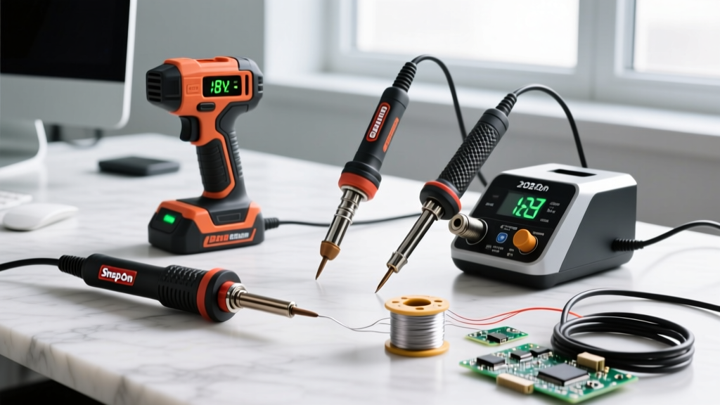
Understanding the temp for soldering also requires understanding the hardware you are using. Budget soldering irons (typically under $40) lack Proportional-Integral-Derivative (PID) temperature controllers. When you touch a cold copper ground plane with a cheap iron, the tip temperature plummets. The user, frustrated by the lack of flow, often cranks the dial to the maximum setting.
This leads to thermal overshoot. Once the iron recovers, it spikes to 450°C or higher, instantly vaporizing the rosin flux into thick, acrid smoke and scorching the component's plastic casing. Investing in a PID-controlled station like the $110 Weller WE1010NA or the professional-grade $350 JBC CD-2BQE ensures that the heater element reacts in milliseconds to thermal loads, maintaining a safe, steady temperature without dangerous spikes.
Health and Safety: Fume Extraction and Burn Prevention
The correct temp for soldering directly impacts operator health. Solder itself does not produce toxic fumes at standard operating temperatures; the danger lies in the flux core. Rosin-based (colophony) fluxes activate between 150°C and 200°C. If your iron is set too high, the flux boils violently, aerosolizing microscopic particulates that are known respiratory sensitizers and can lead to occupational asthma.
The MIT Environment, Health & Safety Soldering Guidelines mandate that soldering must only be performed with adequate ventilation. To maintain a safe environment:
- Use Local Exhaust Ventilation (LEV): A desktop fume extractor with a HEPA and activated carbon filter (such as the Hakko FA-400) must be positioned 6 to 8 inches from the soldering joint to capture the plume before it reaches the operator's breathing zone.
- Wear Safety Glasses: Flux spitting is common when the temp for soldering is too high or when moisture is trapped in the flux core. Molten solder and acidic flux can cause severe corneal damage.
- Tip Maintenance: A blackened, oxidized tip will not transfer heat. Operators often compensate for poor heat transfer by increasing the temperature, creating a vicious cycle of overheating. Always tin your tip with a thin layer of solder before placing it in the holder.
Step-by-Step Thermal Management for High-Mass Joints
When soldering heavy components like TO-220 voltage regulators, large electrolytic capacitors, or thick coaxial connectors, the thermal mass of the component acts as a massive heat sink. Simply raising the temp for soldering on your iron dial is the wrong approach. Instead, follow this safe thermal profiling sequence recommended by the NASA Electronic Parts and Packaging (NEPP) Program for high-reliability assemblies:
- Apply Liquid Flux: Apply a small amount of external no-clean or rosin-activated liquid flux to the joint. This lowers the surface tension and promotes faster wetting, reducing the required dwell time.
- Use the Largest Tip Possible: Thermal transfer is a function of surface area, not just temperature. Swap your fine-point tip for a wide bevel or chisel tip (e.g., a JBC C245-945 or Hakko T18-D24). A larger tip at 350°C transfers heat far more safely and efficiently than a micro-tip cranked to 420°C.
- Pre-Tin the Pad: Apply a small amount of solder to the iron tip and immediately touch it to the pad and component lead simultaneously. The molten solder acts as a thermal bridge, transferring heat into the joint much faster than air or dry metal-to-metal contact.
- Feed Solder to the Joint, Not the Iron: Once the thermal bridge is established, feed your solder wire directly into the joint. If it melts instantly and flows with a smooth, concave fillet, the temperature is correct.
- Remove and Inspect: Remove the iron and allow the joint to cool naturally. Never blow on a lead-free solder joint; forced cooling can cause micro-cracking in the SAC305 crystalline structure.
Real-World Failure Modes from Incorrect Temperatures
Ignoring the optimal temp for soldering leads to distinct, identifiable failure modes on the workbench. Recognizing these signs will help you troubleshoot your technique and protect your equipment.
1. Pad Delamination and Measling
If you notice white, cloudy spots inside the fiberglass of the PCB (measling) or if the copper pad lifts entirely off the board, your temperature or dwell time was far too high. The epoxy binder in the FR-4 substrate undergoes a glass transition (Tg) typically around 130°C to 170°C. Prolonged exposure to 400°C+ destroys the structural integrity of the board.
2. The 'Gummy' or 'Dull' Joint
If the solder forms a ball on the tip and refuses to wet the pad, or if the resulting joint looks dull, gray, and grainy, your temperature is too low, or your tip is severely oxidized. A dull joint indicates a cold solder connection, which will inevitably fail under mechanical vibration or thermal cycling in the field.
3. Component Casing Deformation
Plastic connectors, relay housings, and IC packages have low melting thresholds. If you see the plastic around a pin melting or warping, you are holding the iron on the joint for too long. Step back, let the component cool for 60 seconds, and re-approach with a larger tip rather than higher heat.
Frequently Asked Questions (FAQ)
Why does my solder ball up and roll off the iron tip?
This is almost always caused by an excessively high temp for soldering combined with an oxidized tip. When the iron is too hot, the flux core burns away before it can clean the metal surfaces, and the solder oxidizes instantly, forming a non-wettable crust. Lower your temperature to 330°C, clean the tip on a damp brass sponge, and re-tin it immediately with fresh, flux-cored solder.
Can I use lead-free soldering temperatures on leaded solder?
While you physically can melt Sn63/Pb37 at 380°C, it is highly discouraged. Exposing leaded solder to lead-free temperatures accelerates tip corrosion (especially if using SAC alloys previously) and causes the lead to oxidize rapidly, resulting in brittle, unreliable joints. Always match your iron's temperature profile to the specific alloy you are dispensing.
How do I safely desolder a multi-layer board without burning it?
Desoldering requires more thermal energy than soldering because you are melting a larger volume of alloy while fighting the cooling effect of internal ground planes. Do not increase your iron temp beyond 380°C. Instead, use a dedicated desoldering station (like the Hakko FR-410), apply generous amounts of liquid flux, and use a board preheater to bring the entire PCB ambient temperature up to 100°C. This reduces the thermal delta, allowing the joint to melt safely at lower tip temperatures.