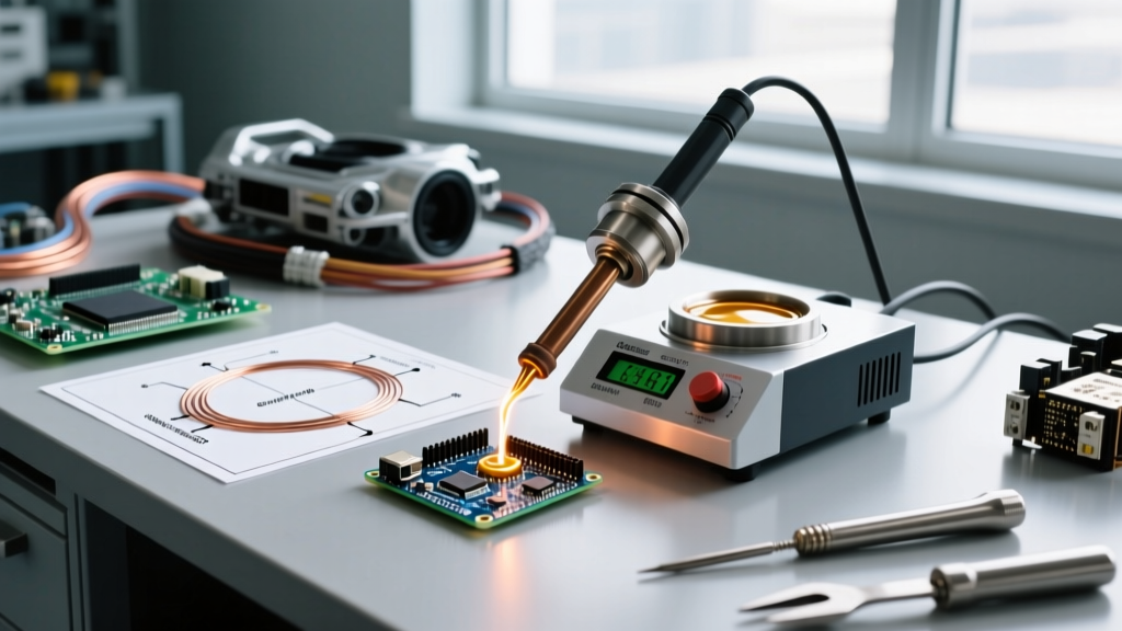

The Thermodynamics of Solder: Why Melting Points Dictate Industry Standards
When materials engineers and PCB designers discuss the melting point of soldering lead, they are rarely referring to pure elemental lead (which melts at 327.5°C / 621.5°F). Instead, industry terminology uses "soldering lead" to describe either the physical wire form factor or, more accurately, the tin-lead (SnPb) alloy family. In 2026, despite the widespread adoption of RoHS-compliant lead-free solders in consumer electronics, leaded alloys remain the undisputed standard in high-reliability sectors. The precise melting point, solidus, and liquidus temperatures of these alloys dictate everything from reflow oven profiles to the selection of hand-soldering stations for mission-critical repairs.
Understanding the thermal behavior of these alloys is not just an academic exercise; it is a fundamental requirement for passing IPC J-STD-001 Class 3 inspections. A miscalculation in thermal profiling leads to cold joints, pad delamination, or catastrophic field failures under thermal cycling.
Pure Lead vs. Eutectic Alloys: Clearing the Terminology
Pure tin melts at 231.9°C, and pure lead melts at 327.5°C. However, when combined, they form a eutectic system. The most famous iteration, Sn63/Pb37 (63% tin, 37% lead), has a single, sharp melting point of exactly 183°C (361°F). Because it transitions from solid to liquid instantly without a "plastic" (semi-solid) phase, it is highly resistant to mechanical disturbance during cooling, making it the gold standard for aerospace and medical electronics.
Comprehensive Industrial Solder Alloy Matrix
The following table outlines the specific thermal properties and primary industrial applications for the most common soldering lead alloys utilized in 2026.
| Alloy Designation | Composition | Solidus (°C) | Liquidus (°C) | Primary Industry Application |
|---|---|---|---|---|
| Sn63/Pb37 (Eutectic) | 63% Sn, 37% Pb | 183 | 183 | Aerospace, Medical, Military (Class 3) |
| Sn60/Pb40 | 60% Sn, 40% Pb | 183 | 190 | General Industrial, Commercial Repair |
| Sn10/Pb90 (High-Temp) | 10% Sn, 90% Pb | 268 | 302 | Automotive Die-Attach, High-Heat Sensors |
| Sn5/Pb92.5/Ag2.5 | 5% Sn, 92.5% Pb, 2.5% Ag | 287 | 296 | Under-Hood Automotive, Power Electronics |
| Indalloy 281 | 62% Sn, 36% Pb, 2% Ag | 179 | 179 | Cryogenic Systems, Low-Temp Substrates |
| SAC305 (Lead-Free Ref) | 96.5% Sn, 3% Ag, 0.5% Cu | 217 | 220 | Consumer Electronics (RoHS Compliant) |
Sector-Specific Applications and Thermal Constraints
Aerospace and Defense: The Tin Whisker Problem
In avionics and satellite communications, the melting point of soldering lead alloys is only half the equation; the metallurgical stability over decades is paramount. The aerospace industry heavily relies on Sn63/Pb37. Why? Because lead-free solders (like SAC305) are highly susceptible to tin whiskers—microscopic, conductive crystalline structures that grow from the tin surface and cause catastrophic short circuits in a vacuum or high-vibration environment. The addition of lead (even at 3%) effectively suppresses tin whisker growth. Furthermore, the 183°C melting point allows for lower thermal stress on sensitive RF components during the wave soldering process.
Automotive Under-Hood: Surviving the Heat Sink
Conversely, standard 183°C eutectic solder would melt or suffer severe creep fatigue near an internal combustion engine or high-voltage EV inverter. For alternator diodes and under-hood sensor arrays, manufacturers utilize high-lead alloys like Sn5/Pb92.5/Ag2.5. With a liquidus of 296°C, this soldering lead variant maintains structural integrity even when ambient under-hood temperatures spike to 150°C and localized component heating pushes junction temperatures past 200°C.
RoHS Exemption Note (2026 Update): Under the European Union's RoHS Directive, specific exemptions (such as Exemption 7(a) and 7(b)) continue to be renewed for critical infrastructure, medical devices, and automotive safety systems. These exemptions legally permit the use of high-lead and eutectic leaded solders where reliable lead-free alternatives with matching thermal and mechanical fatigue profiles do not yet exist.
Troubleshooting Thermal Mismatches in Hand Soldering
Knowing the melting point of your soldering lead is useless if your equipment cannot deliver the necessary thermal energy to the joint. A common failure mode in industrial repair is thermal starvation, which operators often misdiagnose as a "cold joint" caused by bad flux. In reality, the soldering iron tip is losing heat to the PCB's internal copper ground planes faster than the heater core can replenish it.
Equipment Selection for High-Mass PCBs
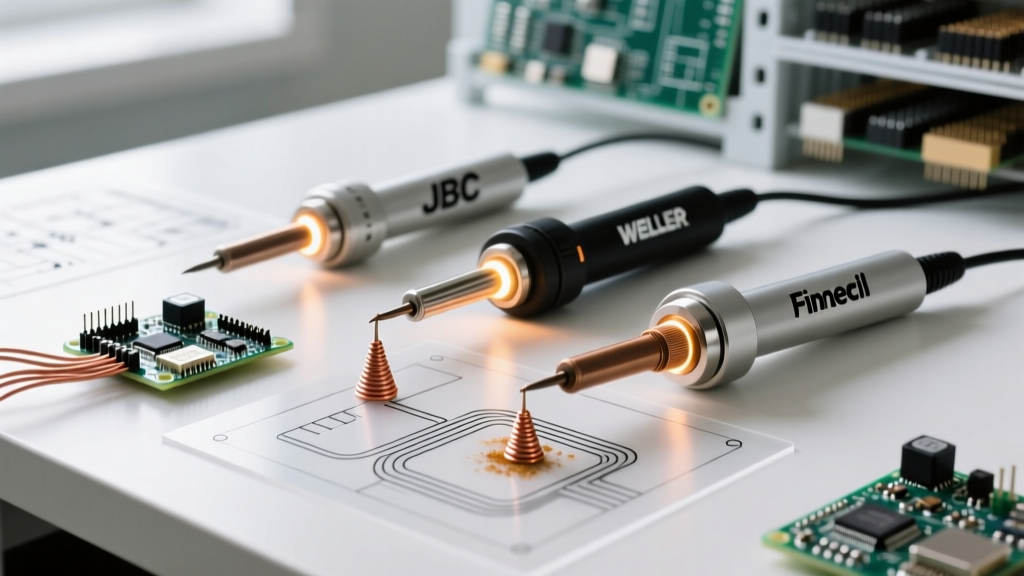
To maintain a stable 183°C (Sn63) or 220°C (SAC305) at the wetting interface, modern industrial facilities have largely abandoned traditional ceramic-heater irons in favor of direct-cartridge heating systems. Below are the industry-standard stations utilized in 2026 for managing complex thermal masses:
- JBC CD-2BQE with C245 Handles: Priced around $680, this station utilizes a cartridge where the heating element is integrated directly into the tip. It detects a temperature drop and delivers peak wattage in under 2 seconds. For heavy ground planes, the JBC C245-945 (2.2mm chisel) is recommended to maximize surface area contact without exceeding the 350°C tip limit that degrades no-clean fluxes.
- Weller WX2021 with RTW2045 Tips: Priced near $1,150, this dual-channel powerhouse is the standard for mixed-technology boards. The RT (Rapid Thermal) micro-tips are essential for 0201 imperial components where the thermal mass is tiny, requiring precise energy delivery to avoid lifting micro-pads.
- Metcal PS-900 (Induction Soldering): Utilizing SmartHeat RF induction technology (approx. $900), Metcal tips self-regulate their temperature based on the Curie point of the tip's internal alloy. If the joint reaches the required thermal threshold, the tip stops heating, virtually eliminating the risk of scorching polyimide flex circuits.
Flux Chemistry and Thermal Activation
The melting point of the soldering lead must be perfectly synchronized with the flux's activation temperature. If you are using a high-temp alloy like Sn10/Pb90 (liquidus 302°C), standard rosin-activated (RA) fluxes will burn off and carbonize long before the solder flows, resulting in severe oxidation and non-wetting.
For high-lead industrial applications, technicians must use high-solids, high-temperature synthetic fluxes (such as Kester 186 or specialized Indalloy tacky fluxes) designed to remain active up to 350°C. Always verify the flux datasheet's "activation range" against your alloy's liquidus point.
Safety and Environmental Compliance
While leaded solders offer superior mechanical and thermal fatigue resistance, they pose significant occupational hazards. The Occupational Safety and Health Administration (OSHA) strictly regulates lead exposure. In industrial settings, the primary risk is not skin contact, but the inhalation of flux fumes that carry microscopic lead particulates. Facilities must employ HEPA and activated carbon fume extraction systems (like the BOFA AD Orbis or Hakko FA-400) positioned within 2 inches of the soldering plume. Furthermore, the Environmental Protection Agency (EPA) mandates strict disposal protocols for solder dross and cleaning solvents contaminated with lead residue.
Frequently Asked Questions (FAQ)
Why does my 60/40 solder melt over a range of temperatures?
Unlike Sn63/Pb37, which is a true eutectic alloy melting instantly at 183°C, Sn60/Pb40 is non-eutectic. It has a solidus of 183°C and a liquidus of 190°C. Between these temperatures, the alloy exists in a "plastic" or pasty state. If the joint is moved during this 7-degree window, it will result in a disturbed joint with a grainy, fractured appearance.
Can I use lead-free soldering tips for leaded solder?
It is highly discouraged. Lead-free solders require higher operating temperatures (typically 350°C - 380°C) and utilize aggressive, highly acidic fluxes to overcome tin's poor wetting characteristics. Tips designed for lead-free soldering often feature thicker iron plating to resist corrosion. Using them at the lower temperatures required for leaded solder (300°C - 320°C) can result in poor thermal transfer and flux carbonization on the tip surface.
How do I test if my solder wire is actually leaded?
In a professional lab, X-ray Fluorescence (XRF) analyzers provide instant, non-destructive alloy verification. On the shop floor, technicians can use chemical lead-testing swabs (like 3M LeadCheck). When crushed and applied to the solder wire, the swab will turn bright pink or red within seconds if elemental lead is present in the alloy.