
Defining Mil Spec Soldering in Modern Electronics
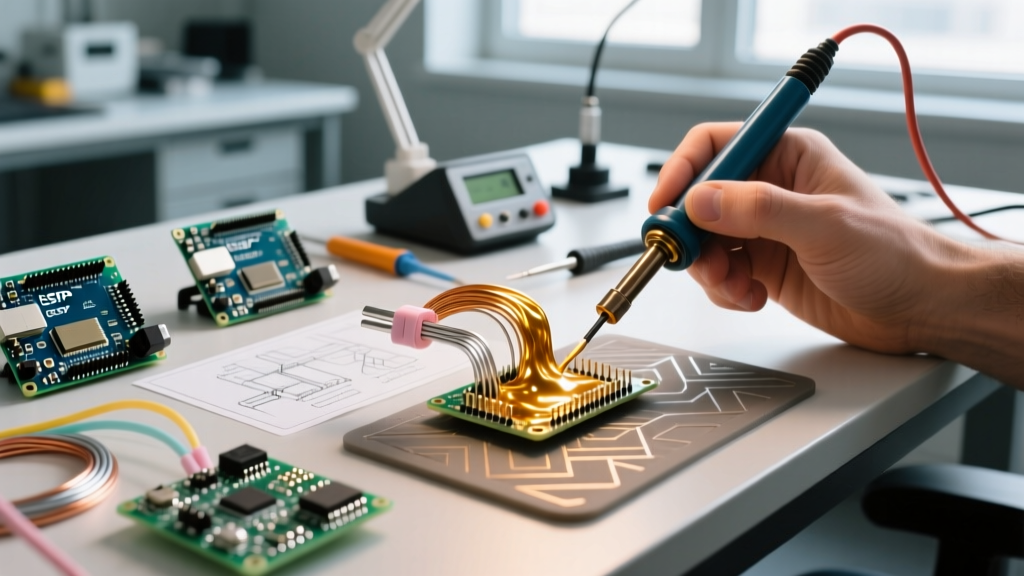
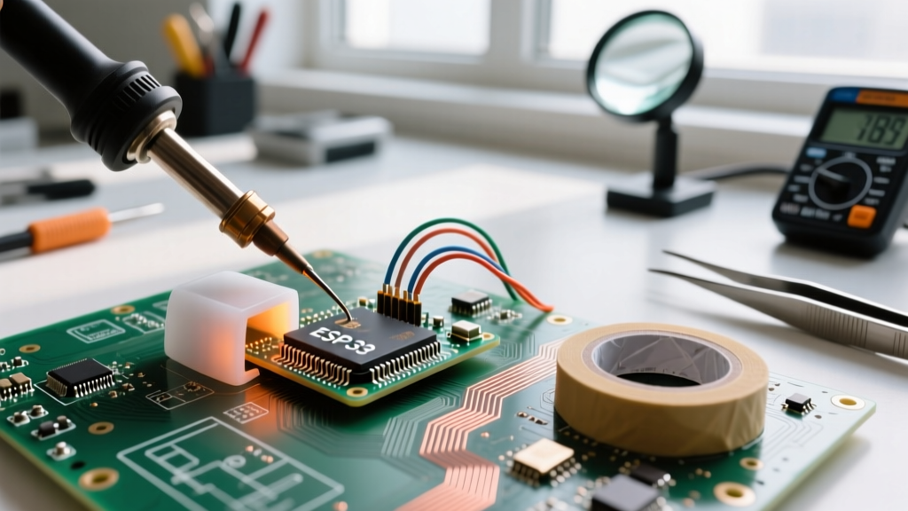
When engineers and defense contractors refer to mil spec soldering, they are invoking a rigorous discipline of high-reliability (hi-rel) electronics assembly. Unlike commercial consumer electronics, where a device's lifespan is measured in a few years and minor cosmetic solder defects are acceptable, mil spec applications—spanning aerospace, defense, medical implants, and deep-space exploration—demand zero-failure tolerances. A single cold joint in a satellite's power distribution unit or a fighter jet's avionics bay can result in catastrophic mission failure.
Historically, the defense industry relied on MIL-STD-2000 (Standard for Soldered Electrical and Electronic Assemblies). However, the Department of Defense canceled this standard in 1996, shifting the burden of quality assurance to industry-consensus standards. Today, true mil spec soldering is governed primarily by IPC J-STD-001 (specifically Class 3) and NASA-STD-8739.3 for soldered electrical connections. Understanding the exact metallurgical, mechanical, and procedural requirements of these standards is critical for any assembly house or DIY engineer tackling hi-rel projects.
The Regulatory Landscape: IPC Class 3 vs. NASA Standards
To execute mil spec soldering correctly, you must understand the acceptance criteria that differentiate high-reliability work from standard commercial work.
- IPC Class 2 (Standard): Allows for partial barrel fill in plated through-holes (PTH) (typically 50%), minor solder wicking, and cosmetic anomalies that do not affect electrical continuity.
- IPC Class 3 (High-Performance): Mandates a minimum of 75% barrel fill for PTH joints, 360-degree wetting on the solder side, and strict prohibition of disturbed joints, dewetting, or non-wetting.
- NASA-STD-8739.3: Takes IPC Class 3 a step further. It requires 100% barrel fill for critical PTH connections, explicit wire wrap termination angles, and strict adherence to flux residue cleaning protocols to prevent electrochemical migration (ECM) in vacuum or high-humidity environments.
Expert Insight: In 2026, the aerospace sector heavily audits assembly houses not just on the final solder joint, but on the process control leading up to it. This includes operator certification (CIS/CSE), daily soldering iron tip calibration, and strict material traceability from the solder spool to the final PCBA.
Essential Equipment for High-Reliability Assembly
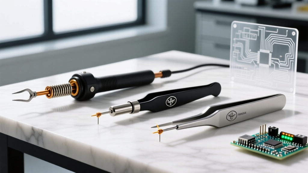
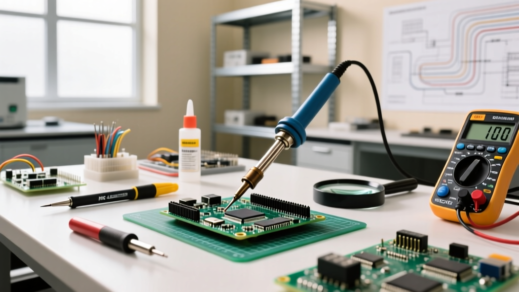
You cannot achieve mil spec tolerances with entry-level $50 soldering irons. High-reliability soldering requires equipment with rapid thermal recovery, precise temperature profiling, and specialized inspection optics. Below is a comparison of industry-standard equipment used in defense contracting.
| Equipment Category | Model / Brand | Approx. Cost (2026) | Key Mil Spec Feature |
|---|---|---|---|
| Soldering Station | Metcal PS-900 | $625 | SmartHeat® RF induction technology; adjusts power based on joint thermal load, not just tip temp. |
| Soldering Station | Weller WX2021 | $890 | 200W power output with active tip temperature verification; essential for heavy ground planes. |
| Inspection Optics | Vision Engineering Mantis Elite | $4,800+ | Ergonomic 3D stereoscopic vision without the eye strain of traditional binocular microscopes. |
| Wire Stripping | Schleuniger EcoStrip 9380 | $2,200 | Laser or precision blade stripping that guarantees zero conductor nicking (per NASA-STD-8739.1). |
| Cleaning Tester | Omegameter 600M | $6,500 | ROSE (Resistivity of Solvent Extract) testing to measure ionic contamination post-cleaning. |
The Metcal SmartHeat Advantage
For mil spec applications, the Metcal PS-900 is a staple. Unlike conventional irons that use a thermocouple to turn a heating element on and off (leading to temperature overshoot and undershoot), Metcal uses Radio Frequency (RF) induction. The tip itself is a ferromagnetic core. When it drops below its Curie temperature, it draws power; when it reaches the exact engineered temperature (e.g., 350°C), it becomes non-magnetic and stops heating instantly. This eliminates the thermal overshoot that can scorch delicate polyimide flex circuits or lift SMD pads.
Metallurgy: Selecting the Right Alloy and Flux
Material selection in mil spec soldering is heavily influenced by the RoHS (Restriction of Hazardous Substances) directive, but with critical exemptions for aerospace and defense due to the tin whisker phenomenon.
Leaded vs. Lead-Free in Aerospace
Pure tin or high-tin lead-free alloys (like SAC305) are prone to growing microscopic, conductive crystalline structures known as tin whiskers. In a densely packed satellite PCB, a tin whisker can bridge two traces, causing a dead short in orbit. Therefore, the defense and aerospace industries utilize a RoHS exemption to continue using Sn63/Pb37 (Tin/Lead) eutectic solder. The addition of 37% lead completely inhibits tin whisker growth.
- Sn63/Pb37 (Eutectic): Melts and solidifies at exactly 183°C (361°F). Ideal for PTH and fine-pitch SMT. Recommended iron temp: 315°C - 350°C.
- Sn96.3/Ag3.7 (Lead-Free Hi-Rel): Used when lead is strictly prohibited (e.g., certain medical or commercial-space applications). Melts at 221°C. Requires higher iron temps (360°C - 385°C) and aggressive no-clean or water-soluble fluxes to overcome poor wetting characteristics.
Flux Chemistry and Cleaning
In commercial assembly, 'No-Clean' fluxes are left on the board. In mil spec soldering, all flux residues must typically be cleaned unless explicitly validated and approved by the end customer. Even 'no-clean' residues can trap moisture and cause dendritic growth or electrochemical migration under extreme thermal cycling. RMA (Rosin Mildly Activated) fluxes, such as Kester 186, are preferred for hand soldering because they provide excellent wetting and are easily removed using saponifiers and ultrasonic or vapor degreasing systems.
Step-by-Step Mil Spec PTH Soldering Procedure
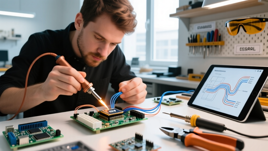
Achieving a compliant Class 3 PTH joint requires a methodical approach. Here is the exact sequence mandated by high-reliability assembly protocols.
- Wire Preparation: Strip the wire using a precision thermal or mechanical stripper. Inspect under 10x magnification. Acceptance criteria: Zero nicks, scrapes, or stretched strands. If more than 10% of the strands are damaged, the wire must be scrapped and re-prepped.
- Tinning: Tin the stripped wire and the component lead using a separate 'tinning pot' or a dedicated tinning iron to prevent cross-contamination of the assembly iron tip.
- Insertion & Seating: Insert the component. The component body must sit flush against the PCB (or at a specified standoff height for high-voltage creepage). Bend the leads slightly (clinched) to prevent the component from lifting during soldering.
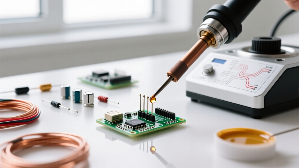
- Thermal Profiling: Apply the iron tip to the land and the lead simultaneously. Feed Sn63/Pb37 solder into the joint, not directly onto the iron tip. The solder should flow via capillary action into the barrel.
- Time Limit: The entire soldering cycle for a single PTH joint should not exceed 3 to 4 seconds. Prolonged heat will delaminate the PCB substrate or damage the component's internal die-attach.
- Cooling: Allow the joint to cool naturally. Never use compressed air or blow on the joint. Forced cooling causes micro-cracking in the solder grain structure.
Inspection Criteria and Common Failure Modes
Under a microscope (minimum 10x magnification), a mil spec solder joint must exhibit a smooth, shiny, concave fillet with a wetting angle of less than 90 degrees (ideally less than 45 degrees). Here are the most common failure modes that will result in a scrapped board during IPC Class 3 inspection:
1. Disturbed Joint
Appearance: Frosty, dull, or crystalline surface.
Cause: The component or wire moved while the solder was in its plastic (semi-solid) state during cooling.
Correction: Reheat the joint to a full liquid state and hold the component perfectly still until it solidifies. Do not simply 'melt the surface'; the entire joint mass must reflow.
2. Solder Wicking
Appearance: Solder travels far up the insulation or the bare wire strands, away from the termination point.
Cause: Excessive heat applied to the wire rather than the terminal, or using a wire stripper that embedded flux too deeply.
Impact: Wicking creates a rigid section of wire. In high-vibration environments (like a missile or aircraft), the wire will fatigue and snap exactly at the boundary where the flexible wire meets the wicked, rigid solder.
3. Non-Wetting vs. Dewetting
Non-Wetting: The solder balls up on the surface with a contact angle greater than 90 degrees. The base metal was not clean or oxidized.
Dewetting: The solder initially wets the surface but then pulls back into islands, leaving a thin, discontinuous film of solder. This is often caused by metallic impurities or severe outgassing from the PCB substrate.
Cleanliness Validation: ROSE Testing
In mil spec environments, visual inspection of cleanliness is insufficient. Invisible ionic residues (like bromides or chlorides from flux activators or human sweat) will absorb atmospheric moisture and create conductive pathways. Assembly houses use ROSE (Resistivity of Solvent Extract) testing. The PCB is washed in a solution of 75% isopropyl alcohol and 25% deionized water. The equipment measures the change in the solution's resistivity. To pass mil spec requirements, the ionic contamination must be strictly below 6.45 µg of NaCl equivalent per square centimeter. For further testing methodologies and hi-rel reliability data, engineers frequently reference technical papers published by the Surface Mount Technology Association (SMTA).
Summary
Mil spec soldering is not merely about making an electrical connection; it is about engineering a metallurgical bond that will survive thermal shock, extreme vibration, and decades of operational life. By adhering strictly to IPC J-STD-001 Class 3 and NASA-STD-8739.3, utilizing RF induction temperature control, selecting eutectic Sn63/Pb37 alloys to prevent tin whiskers, and enforcing rigorous ROSE cleanliness testing, technicians ensure that high-reliability electronics perform flawlessly when failure is not an option.