
The Hidden Hazards of High-Density PCB Rework
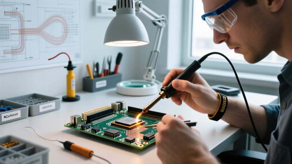
Repairing or modifying a modern soldered motherboard in 2026 requires far more than a steady hand and a basic iron. Contemporary computing boards feature 14-to-18-layer FR-4 laminates, buried micro-vias, and ultra-fine-pitch BGA (Ball Grid Array) packages housing 3nm silicon dies. A single mistake in thermal application, electrostatic discharge, or chemical handling can instantly destroy a $1,500 component or pose severe health and safety risks to the technician. Whether you are replacing a corrupted BIOS SPI chip, reballing a Southbridge PCH, or swapping out a shorted MLCC capacitor near the CPU VRM, strict adherence to safety protocols is non-negotiable.
ESD Mitigation: Protecting the Silicon Die
Electrostatic Discharge (ESD) is the silent killer of motherboard components. While the human body typically cannot perceive a static shock until it reaches approximately 3,000 volts, modern nano-scale silicon architectures on a soldered motherboard can suffer catastrophic gate oxide breakdown at less than 10 volts. According to the ESD Association, latent ESD damage can cause a component to pass initial testing but fail prematurely in the field due to electromigration.
Expert Insight: Never trust a makeshift ground wire clipped to a radiator. Proper ESD mitigation requires a controlled, high-resistance path to earth ground to prevent rapid discharge while safely bleeding off static accumulation.
Mandatory ESD Workbench Configuration
- Dissipative Matting: Use a dual-layer ESD mat, such as the Desco 2312 Statfree T2 Plus (approx. $85). The top layer should be static-dissipative (10^6 to 10^9 ohms), while the bottom layer is conductive.
- Wrist Straps and Monitoring: Wear a 1-megohm current-limiting wrist strap. For critical BGA rework, invest in a continuous monitor like the Hakko 498B ($140), which alarms instantly if the ground connection breaks.
- Ionization: Low-humidity environments (below 30% RH) generate massive triboelectric charges on plastic flux bottles and Kapton tape. Use an active ionizing blower (e.g., Simco-Ion Top Gun) to neutralize insulators that cannot be grounded.
Thermal Management and BGA Rework Safety
Applying localized heat to a soldered motherboard introduces severe mechanical stress. The coefficient of thermal expansion (CTE) mismatch between the silicon die, the organic substrate, and the copper pads can lead to 'pad cratering'—a failure mode where the copper pad rips out of the fiberglass laminate, permanently destroying the motherboard trace.
Thermal Thresholds for Motherboard Materials
| Material / Component | Critical Temperature Threshold | Failure Mode if Exceeded |
|---|---|---|
| FR-4 Laminate (Standard Tg) | 130°C - 150°C | Delamination, warping, via barrel cracking |
| FR-4 Laminate (High Tg) | 170°C - 180°C | Loss of mechanical rigidity, pad cratering |
| SAC305 Lead-Free Solder | 217°C - 220°C (Melting) | Liquidus phase; component shifting if bumped |
| Electrolytic VRM Capacitors | 105°C (Prolonged Exposure) | Electrolyte boil-off, venting, explosion risk |
| Silicon Die (Peak Reflow) | 260°C (Max 10 seconds) | Silicon lattice damage, wire bond melting |
Pre-Heating and Hot Air Protocols
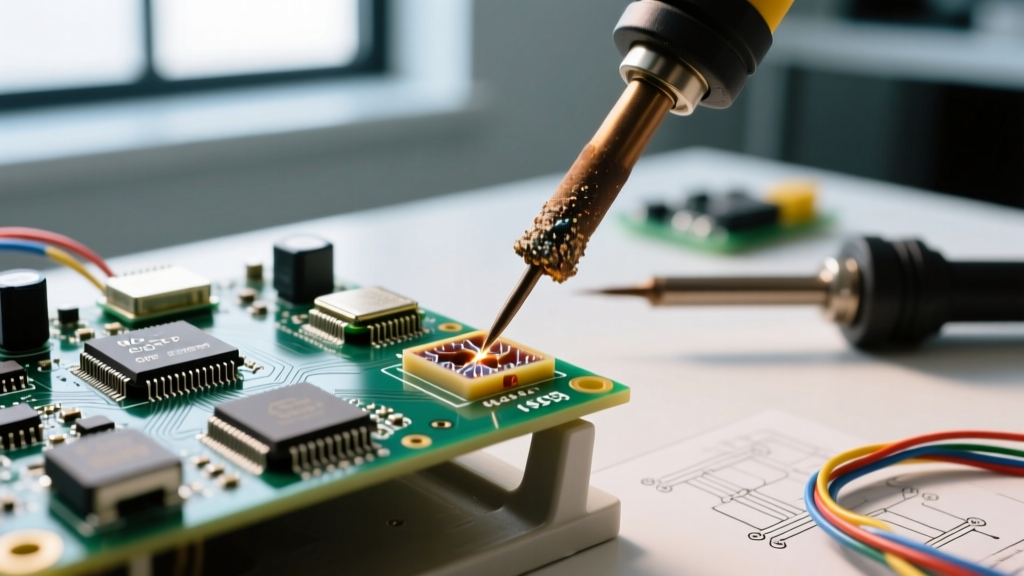
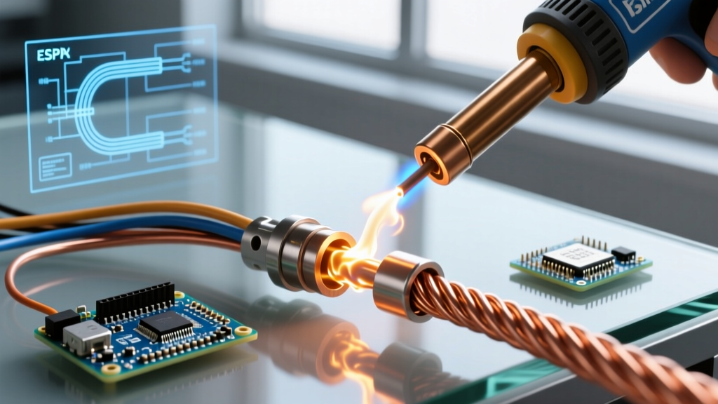
Never apply a 400°C hot air pencil directly to a cold motherboard. The thermal shock will instantly crack multi-layer ceramic capacitors (MLCCs) in the vicinity. You must use an IR or quartz pre-heater, such as the Hakko FR-830 ($900), to bring the entire PCB to a baseline of 120°C to 130°C. Once pre-heated, use a precision station like the Quick 861DW 1000W ($350) with a 12mm nozzle set to 320°C and an airflow of 30L/min to reflow the specific BGA area. This minimizes the thermal gradient across the board.
Fume Extraction and Chemical Safety
Soldering on a motherboard requires generous amounts of flux to break through the heavy oxidation of lead-free factory solder joints. Most rosin-based and synthetic no-clean fluxes contain colophony (pine resin) or synthetic resins that vaporize at soldering temperatures. The UK Health and Safety Executive explicitly identifies colophony fumes as a severe respiratory sensitizer, capable of inducing irreversible occupational asthma and chronic contact dermatitis.
Engineering Controls for Fume Mitigation
- Source Extraction: A simple desk fan blowing fumes away is entirely inadequate and merely redistributes toxic particulates. You must use a localized HEPA and activated carbon extraction system. The Hakko FA-400 ($65) is suitable for light hobbyist use, but professional labs should utilize the BOFA AD362 ($1,800+), which features a multi-stage filtration system specifically designed to capture sub-micron flux particulates and volatile organic compounds (VOCs).
- Flux Selection: When possible, use low-VOC, halide-free no-clean fluxes (e.g., Amtech NC-559-V2-TF). If you must use water-soluble flux (like Kester 331) for heavy oxidation, remember that it is highly conductive and corrosive. It must be scrubbed off with heated deionized (DI) water and the board baked at 80°C for 4 hours to prevent dendritic shorting between 0201 SMD pads.
Electrical Isolation and Capacitor Discharge
Before applying any heat or multimeter probes to a soldered motherboard, all stored electrical energy must be safely bled. Motherboards contain large primary filter capacitors in the power delivery network (PDN) and CMOS supercapacitors that can retain dangerous or component-damaging charges long after the battery and AC adapter are removed.
The Safe Discharge Procedure
Never short a charged capacitor with a metal screwdriver. The instantaneous current spike can vaporize the screwdriver tip, damage your retinas with an arc flash, and destroy the delicate PCB traces connected to the capacitor.
- Construct a Bleed Tool: Solder a 100-ohm, 5-watt ceramic power resistor between two insulated alligator clips. This specific resistance value safely bleeds a 20V/3000µF capacitor down to safe levels in under two seconds without generating excessive heat or current spikes.
- Verify with a Multimeter: Use a true-RMS meter like the Fluke 87V. Set it to DC Volts and probe the positive and negative terminals of the main VRM bulk capacitors. Wait until the reading drops below 0.05V before proceeding with physical rework.
Pre-Power Diagnostics: Preventing the 'Magic Smoke'
After completing your soldering rework, never immediately plug the motherboard into a power supply. According to the IPC-7711/7721 standard for rework and repair, post-repair verification is mandatory to prevent catastrophic secondary damage caused by accidental solder bridges.
Set your multimeter to Diode Mode. Place the red probe on a known ground point (like a USB port shield or mounting hole) and use the black probe to measure the CPU VCC, RAM VDDQ, and PCH VCC rails. A healthy motherboard will typically show a body-diode voltage drop between 0.300V and 0.600V on these rails. If your multimeter reads 0.000V (a dead short), you have a solder bridge under a BGA chip or a cracked MLCC capacitor. Applying 12V to a shorted rail in this state will instantly burn through the PCB's internal copper planes, turning a repairable board into e-waste.
Summary Checklist for the Workbench
- [ ] ESD mat grounded via 1-megohm resistor; wrist strap tested.
- [ ] Motherboard pre-heated to 120°C baseline before localized hot air application.
- [ ] Active HEPA/Carbon fume extractor positioned within 2 inches of the solder joint.
- [ ] VRM capacitors bled using a 100Ω 5W resistor tool.
- [ ] Diode-mode multimeter checks performed on all modified power rails prior to first boot.