
Mastering Magnifying Glass Soldering: Beyond the Basics
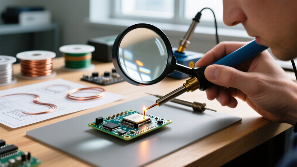
Transitioning from standard through-hole components to fine-pitch Surface Mount Devices (SMD) requires more than just a steady hand; it demands optical precision. While high-end stereo microscopes are the gold standard for PCB rework, a high-quality magnifying glass or visor remains the workhorse for hobbyists, field technicians, and DIYers. However, magnifying glass soldering introduces unique optical and thermal challenges that can ruin joints, damage equipment, and cause severe eye strain.
In this comprehensive troubleshooting guide, we address the most frequent failure modes encountered when using optical magnification for soldering, providing actionable, physics-based solutions to optimize your 2026 workbench setup.
The Working Distance vs. Magnification Trap
The most common complaint among beginners is: "My soldering iron hits the lens before the tip touches the solder pad." This occurs because of the inverse relationship between magnification power and focal length. As magnification increases, the working distance (the space between the lens and the PCB) shrinks dramatically.
| Magnification | Approx. Diopter | Working Distance | Best Application |
|---|---|---|---|
| 2.0x | +4 | 10 inches (25 cm) | Standard through-hole, wire splicing, large SMD (1206) |
| 3.0x | +8 | 5 inches (12.5 cm) | 0805 / 0603 SMD components, basic PCB inspection |
| 5.0x | +16 | 2.5 inches (6.5 cm) | Inspection only, micro-soldering with specialized tips |
| 10.0x | +32 | 1.2 inches (3 cm) | Jewelry, microscope inspection (Not for active soldering) |
Troubleshooting: Iron Collision and Bulkiness
If you are using a 5x lens and a standard chisel tip on a bulky iron (like a classic Weller WES51), the heater core will physically strike the magnifying glass. The Fix: You must pair high-magnification lenses with micro-pencil tips. For example, if you use a modern Weller WE1010NA station, swap the standard ETA tip for an RT1 micro-pencil tip. The RT1 extends further from the heater core, granting you the necessary clearance to solder under a 3x or 5x lens without collision.
Alternatively, adopt the "Inspect-Solder-Inspect" workflow: use a 5x or 10x lens to place the component and apply flux, swing the magnifier away, solder with the naked eye or a 2x visor, and swing the high-power lens back to inspect the fillet against SparkFun's SMD workmanship guidelines.
Troubleshooting Thermal Shimmer and Lens Damage
When you apply 350°C+ heat to a PCB, the air above the joint rapidly expands, creating a thermal plume. This plume alters the refractive index of the air, causing a "mirage" or shimmering effect when viewed through a magnifying glass. This thermal shimmer makes it nearly impossible to track the solder flow on fine-pitch IC pins.
Eliminating the Mirage Effect
Do not attempt to blow the heat away with your breath; this introduces moisture and causes inconsistent cooling. Instead, integrate a localized fume extractor. Position a unit like the Hakko FA-400 (approximately $75) at a 45-degree angle to the workpiece. The goal is to pull the thermal plume laterally away from your optical axis, rather than pulling it straight up through your line of sight.
Preventing Acrylic Lens Melting
Most budget magnifying glasses (under $40) use acrylic or polycarbonate lenses. These materials have low melting points and can warp or permanently cloud if exposed to radiant heat from a soldering iron or hot air rework station over time.
Pro-Tip: If your working distance is less than 6 inches, you must upgrade to a borosilicate glass lens. Glass is impervious to soldering temperatures and resists scratching from accidental flux splatter. Models like the AmScope SE400-Z boom-arm stand ($130-$150) offer interchangeable glass lenses specifically designed for thermal environments.
Lighting Glare and Shadow Elimination
Magnification concentrates light, but it also amplifies glare. A poorly lit workspace will force your pupils to dilate, drastically reducing your depth of field and making stereoscopic soldering a frustrating chore.
- The Ring Light Reflection Problem: Placing a standard LED ring light directly above a convex magnifying glass creates a blinding white hotspot in the center of your vision. Solution: Use a diffused ring light (like the AmScope LED-100SD) or bounce the light off a white foam-core reflector to create soft, omnidirectional illumination.
- The Iron Shadow: If your primary light source is directly overhead, your soldering iron will cast a harsh shadow exactly where you need to see. Solution: Implement dual-arm gooseneck LED lights positioned at 3 o'clock and 9 o'clock, angled at 45 degrees toward the PCB. This cross-lighting eliminates shadows and highlights the texture of the solder fillet.
- Color Rendering Index (CRI): Ensure your bench lights have a CRI of 90 or higher. Low-CRI LEDs make it incredibly difficult to distinguish between a cold, grainy solder joint and a shiny, properly wetted joint.
Ergonomics: Head-Mounted vs. Boom-Arm Stands
Neck and back fatigue are the silent killers of precision electronics work. Choosing the wrong mounting style for your magnifying glass will lead to physical strain and shaky hands.
Head-Mounted Visors (e.g., Donegan OptiVISOR DA-10)
Visors (approx. $55) are excellent for keeping both hands free and maintaining a natural, binocular field of view. However, they require you to hold your head perfectly still to maintain focus. Failure Mode: Leaning in to get a closer look shifts the focal plane, causing instant blur. You must move your torso, not just your neck, to maintain the exact focal distance.
Boom-Arm Stands (e.g., Elenco SE-301 or AmScope)
Boom arms clamp to your desk and hover over the PCB. They allow you to rest your wrists on the bench, dramatically improving hand stability for 0402 SMD work. Failure Mode: Cheap friction-based boom arms slowly droop under the weight of the glass lens, shifting focus mid-solder. Always invest in a stand with mechanical tension knobs or gas-spring counterbalances.
Rapid-Fire Troubleshooting FAQ
Q: Why do my eyes fatigue and cross after 20 minutes of using a single magnifying lens?
A: This is caused by binocular disparity. When you use a single magnifying glass, one eye looks through the lens (seeing a magnified, bright image) while the other eye looks around it (seeing a smaller, dimmer image). Your brain struggles to fuse these two conflicting signals, leading to rapid optical fatigue. Fix: Switch to a binocular visor with dual lenses, or use an eye-patch over the non-dominant eye if you must use a single-lens loupe.
Q: Can I use my magnifying glass while using a hot air rework station?
A: Absolutely not. Hot air stations (like the Quick 861DW) output air at 350°C+ at high velocities. This will instantly warp acrylic lenses, and the intense thermal turbulence will make the magnified image completely unusable. For hot air rework, you must rely on a high-temperature stereo microscope or the naked eye.
Q: How do I clean burnt flux residue off my magnifying glass without ruining it?
A: Never use acetone, nail polish remover, or abrasive paper towels. Acetone will chemically melt acrylic and polycarbonate lenses, turning them cloudy permanently. Instead, use 99% Isopropyl Alcohol (IPA) and a high-quality optical microfiber cloth. Spray the IPA onto the cloth—not the lens—to prevent liquid from seeping into the bezel hinges.
Q: Is it safe to solder without safety glasses if I'm wearing a magnifying visor?
A: No. While magnifying visors provide a physical barrier, they are not rated for high-impact ANSI Z87.1 safety standards. Soldering can produce microscopic splatters of molten solder or snapping wire clippings that can bounce around the edges of a visor. According to OSHA's eye and face protection standards, secondary impact protection is required. Wear wrap-around safety goggles underneath your magnifying visor, or ensure your magnifying glass is mounted on a boom arm and wear standard ANSI-rated safety glasses.
Final Workbench Optimization
Successful magnifying glass soldering is less about the magnification power and more about the integration of optics, lighting, and thermal management. By matching your diopter rating to the correct working distance, upgrading to borosilicate glass, and implementing cross-lighting, you can achieve near-microscopic precision on a DIY budget. For further reading on setting up an ergonomic and safe electronics workstation, review the comprehensive tool guides provided by the Adafruit Learning System.