
The Pre-1992 Landscape: When the Military Dictated Soldering
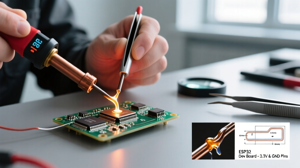
Before the electronics industry adopted unified commercial standards, soldering workmanship was governed by rigid, prescriptive military specifications. Throughout the 1970s and 1980s, MIL-STD-2000A and MIL-S-45743 were the undisputed bibles for aerospace and defense contractors. These documents did not merely define what a reliable solder joint should look like; they dictated the exact angle of the soldering iron, the precise dwell time, and the mandatory use of specific rosin-based flux chemistries.
While this prescriptive approach ensured high reliability for mission-critical defense hardware, it became a massive bottleneck for the booming commercial electronics sector of the late 1980s. Commercial manufacturers needed agility. Waiting years for the Department of Defense to update a standard to accommodate new surface-mount technology (SMT) or finer-pitch components was commercially unviable. Furthermore, the mandatory post-solder solvent cleaning processes dictated by military specs began damaging early plastic IC packages and thin flexible substrates. The industry desperately needed a performance-based standard driven by commercial consensus, not military mandate.
1992 and the Birth of IPC J-STD-001 Soldering Certification
The pivotal shift occurred in 1992 when the Institute for Interconnecting and Packaging Electronic Circuits (IPC) and the Electronic Industries Alliance (EIA) jointly published the first iteration of the J-STD-001. This was a watershed moment for the IPC J-STD-001 soldering certification ecosystem. Unlike its military predecessors, J-STD-001 shifted the paradigm from prescriptive methodology to performance-based acceptance criteria.
'The transition from MIL-STD-2000 to J-STD-001 allowed manufacturers to innovate their assembly processes while maintaining strict, verifiable reliability metrics for the final solder joint.' — Surface Mount Technology Association (SMTA) Historical Archives.
This evolution meant that as long as the final solder joint met the visual and metallurgical criteria for wetting, fillet formation, and cleanliness, the manufacturer was free to use automated selective soldering, custom reflow profiles, or manual techniques that best suited their specific production line.
Evolution of the Standard: A Revision-by-Revision Breakdown
To understand the current 2026 training landscape, one must examine how the standard adapted to three decades of technological disruption. Below is a matrix detailing the major revisions and the industry catalysts that drove them.
| Revision | Release Year | Primary Industry Catalyst | Key Technical Additions |
|---|---|---|---|
| Rev A | 1996 | Early SMT Adoption | Refined SMT pad coverage criteria; initial cleanliness testing protocols. |
| Rev B | 2000 | Global Environmental Awareness | Preparation for lead-free transitions; updated wire preparation specs. |
| Rev C | 2003 | RoHS Directive Impending | Formal integration of lead-free alloy acceptance criteria (e.g., SAC305). |
| Rev D | 2005 | Lead-Free Mandate | Distinct visual criteria for lead-free vs. tin-lead fillets; grain structure analysis. |
| Rev E | 2010 | Bottom-Termination Components | X-ray inspection criteria for BGAs; head-in-pillow defect definitions. |
| Rev F | 2014 | High-Density Interconnects | Micro-BGA standards; selective soldering process controls. |
| Rev G | 2017 | Automotive and Medical Boom | Introduction of Class 3A (Aerospace) and Medical addendums; strain relief requirements. |
| Rev H | 2022 | Extreme Miniaturization | Criteria for 01005 and 008004 passives; conformal coating interaction with flux residues. |
The Lead-Free Paradigm Shift (Rev C and D)
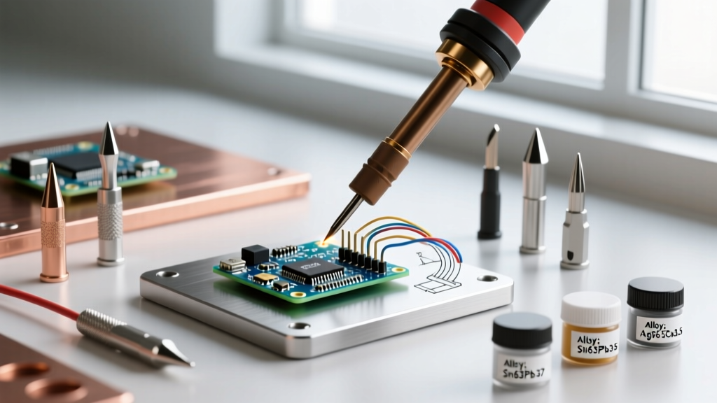
The most turbulent era in the history of IPC certification was the transition to lead-free soldering, driven by the European Union's RoHS directive. Soldering professionals had to completely relearn wetting behaviors. Traditional tin-lead (Sn63Pb37) flows effortlessly at 183°C, exhibiting a shiny, smooth fillet. Lead-free alloys like SAC305 (Sn96.5Ag3.0Cu0.5) require higher reflow temperatures (217°C+) and often result in dull, grainy fillets that were previously rejected as cold joints under older revisions. Revisions C and D fundamentally rewrote the visual inspection criteria to prevent false rejections of perfectly reliable lead-free joints.
Miniaturization and Advanced Packaging (Rev G and H)
As of the current Rev H baseline, which governs 2026 certifications, the standard heavily addresses miniaturization. Soldering 01005 (0.4mm x 0.2mm) chip components requires microscopic precision. The standard now includes stringent guidelines on solder volume, standoff height, and the use of advanced microscopy (up to 40x magnification) for inspection, moving far beyond the traditional 10x loupe mandated in the 1990s.
The Cost of Non-Compliance: ECM and Tin Whiskers
Why do modern manufacturers invest heavily in this certification? The answer lies in catastrophic field failure modes. Under Rev H, strict guidelines govern the handling of no-clean flux residues. If a technician improperly applies a conformal coating over an activated, uncleaned no-clean flux residue, it can trap moisture and lead to Electrochemical Migration (ECM), causing short circuits in high-impedance medical devices. Furthermore, improper handling of pure tin finishes without adequate stress-relief protocols can accelerate tin whisker growth, a major concern documented extensively by the NASA Electronic Parts and Packaging (NEPP) Program.
The 2026 Certification Ecosystem: CIS, CIT, and CSE
The IPC certification structure has evolved into a highly specialized, tiered ecosystem. Understanding these tiers is critical for engineering managers and DIY enthusiasts looking to professionalize their skills.
- Certified IPC Specialist (CIS): The baseline for operators and technicians. Focuses on practical soldering skills and visual inspection. In 2026, a 4-day CIS course typically costs between $1,200 and $1,800, depending on the training center and whether materials are included.
- Certified IPC Trainer (CIT): Required for individuals who will train and certify CIS operators within their own company. A CIT course requires deep knowledge of the standard's intent and takes about 5 days, costing roughly $2,500 to $3,200.
- Company Soldering Engineer (CSE): A newer, advanced tier focusing on process engineering, defect root-cause analysis, and Statistical Process Control (SPC) for high-volume soldering lines.
Actionable Guide: Sponsoring J-STD-001 Training in 2026
If you are procuring training for your team or upgrading your in-house lab to meet IPC validation, the hardware and curriculum requirements have become highly specific.
Equipment Requirements for Modern IPC Labs
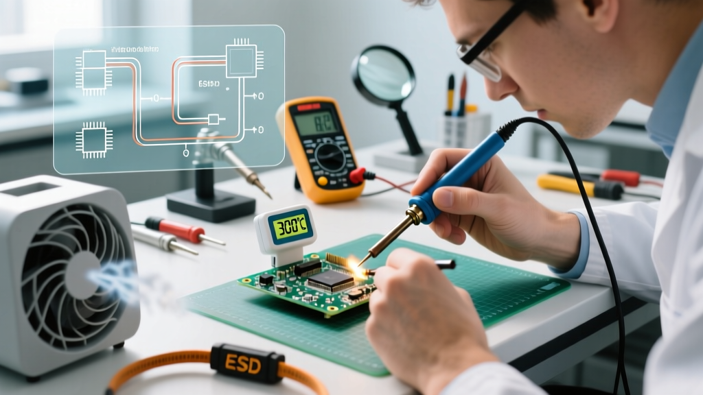
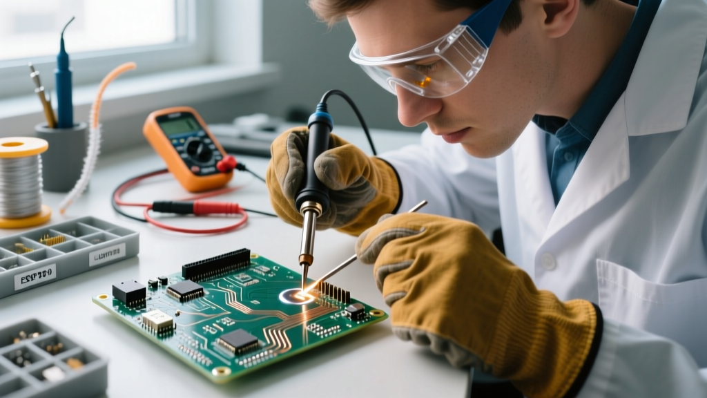
To pass the practical CIS modules in 2026, training centers must provide equipment capable of handling both high-thermal-mass through-hole joints and ultra-fine-pitch SMT rework. Standard 40W irons are no longer sufficient. Modern IPC-validated labs utilize:
- Active-Tip Soldering Systems: Units like the JBC CD-2BQF or Weller WXMP microsoldering handpieces are mandatory for 0201 and 01005 component modules. These systems offer sub-second thermal recovery, crucial for preventing pad lifting on modern, delicate FR-4 and polyimide flex substrates. Technicians must master specific tip geometries, such as the JBC C115-101 nano-blade, for micro-BGA rework.
- Fume Extraction: Compliance with local OSHA and IPC lab safety guidelines requires source-capture fume extraction (e.g., Metcal BVX-200) to manage the aggressive volatile organic compounds (VOCs) in modern water-soluble and no-clean fluxes.
- Optical Inspection: Digital microscopes with built-in measurement reticles, such as the AmScope SM-4TZ-144A, are now standard for verifying fillet dimensions against Rev H tolerances.
Frequently Asked Questions (FAQ)
Does IPC J-STD-001 certification expire?
Yes. A CIS or CIT certification is valid for exactly two years from the date of passing the practical and written exams. Recertification requires a shorter, 2-day modular update course that covers any interim standard revisions or technical clarifications issued by the IPC Technical Committee.
Can I use J-STD-001 for lead-free and tin-lead mixed assemblies?
Yes, but it requires strict process segregation. The standard explicitly outlines the acceptance criteria for mixed-metal joints. However, in 2026, most Class 3 environments strictly forbid intentional mixing due to the risk of bismuth or lead contamination lowering the eutectic melting point and causing field failures under thermal cycling.
What is the difference between IPC J-STD-001 and IPC-A-610?
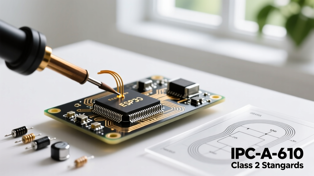
Think of J-STD-001 as the recipe and process standard, while IPC-A-610 is the photo album for final inspection. J-STD-001 dictates the materials, flux types, and process controls required during assembly. IPC-A-610 provides the visual acceptance criteria for the completed electronic assembly. Most certified professionals hold both to ensure end-to-end quality control.