
Why Soldering Beats Quick Connectors for LED Strips
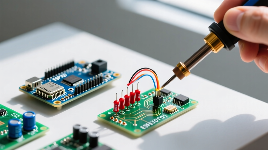
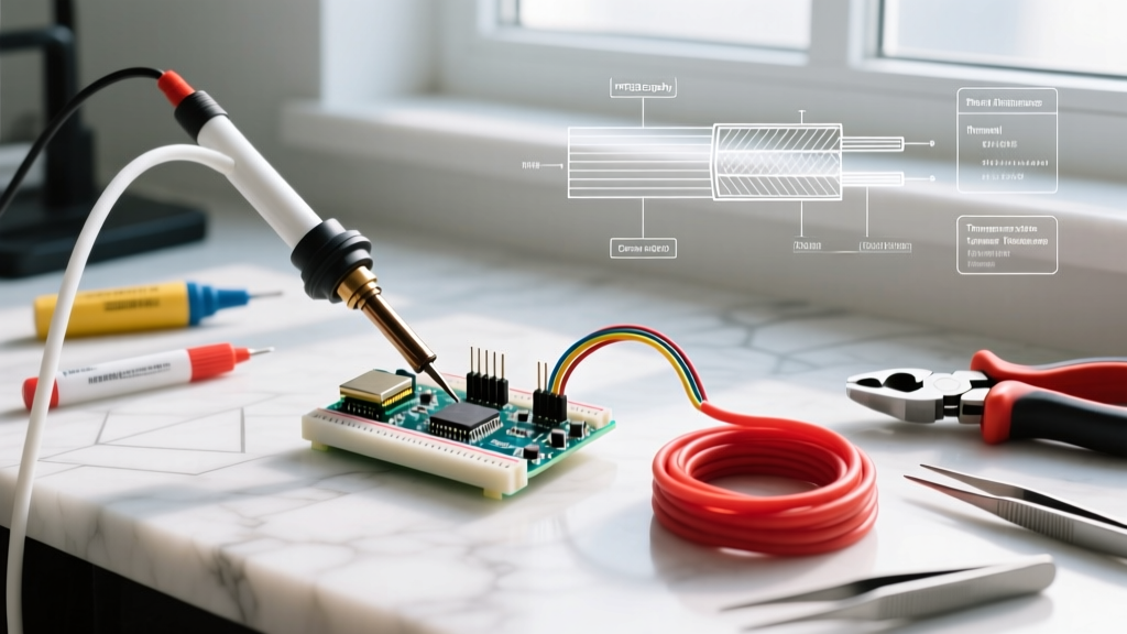
In the modern lighting landscape of 2026, LED strip lights—ranging from high-density COB (Chip-on-Board) arrays to addressable WS2812B NeoPixels—are ubiquitous in architectural and DIY projects. While the market is flooded with "solderless" quick connectors (like the LC1/LC2 punch-down styles), experienced electrical DIYers know that soldering LED strip lights remains the undisputed gold standard for reliability.
Quick connectors rely on microscopic metal teeth piercing the flexible printed circuit board (FPCB) to make contact. Over time, thermal expansion and contraction cause these teeth to lose grip, leading to high-resistance connections, localized voltage drops, and eventual failure. Soldering, by contrast, creates a permanent metallurgical bond. When executed correctly, a soldered joint on a strip light will easily outlast the LEDs themselves, handling high current loads without generating parasitic heat.
Essential Toolkit for 2026 LED Projects
Soldering LED strips requires precision. The copper pads on an FPCB are exceptionally fragile; too much heat will delaminate the adhesive backing and lift the pad entirely. To prevent this, you need a temperature-controlled setup and the right chemistry.
- Soldering Iron: A temperature-controlled station is mandatory. The Hakko FX-888D (approx. $115) or the portable Pinecil V2 (approx. $28) are excellent choices. Use a micro-pencil tip (e.g., Hakko T18-B or Pinecil TS-B2) for tight 5050/2835 SMD pads.
- Solder Wire: Use 63/37 (tin/lead) eutectic rosin-core solder with a thin diameter of 0.5mm (0.020"). Eutectic solder transitions instantly from liquid to solid, preventing "cold joints" caused by micro-movements during cooling. Avoid lead-free solder for FPCB work, as its higher melting point (approx. 217°C vs 183°C) drastically increases the risk of thermal damage to the strip.
- Flux: Do not rely solely on the rosin core inside your solder. Apply a dedicated no-clean tacky flux like MG Chemicals 8341 or Chip Quik NC191. Flux lowers the surface tension of the molten solder, allowing it to wick onto the pad in under two seconds.
- Wire: 22 AWG or 24 AWG stranded silicone wire. Silicone insulation won't melt or shrink back when your iron gets close to the strip.
Wire Gauge and Current Capacity Matrix
Choosing the wrong wire gauge for your jumper cables or main power feeds is a common cause of LED dimming and flickering. Refer to the matrix below to match your wire to the specific LED strip's current draw.
| Wire Gauge (AWG) | Max Continuous Current | Best Use Case on LED Strips |
|---|---|---|
| 18 AWG | ~10 Amps | Main power feeds for high-density 24V COB strips (5m+ runs) |
| 20 AWG | ~5 Amps | Main feeds for standard 12V SMD 5050 RGB strips |
| 22 AWG | ~2.5 Amps | Corner jumps, WS2812B data/power pigtails, short interconnects |
| 24 AWG | ~1.5 Amps | Low-current addressable data lines, 5V low-density pixel jumps |
Step-by-Step: Soldering SMD and WS2812B Pads
Whether you are working with analog 12V RGB strips or 5V addressable WS2812B strips, the physical soldering technique on the copper pads remains identical. According to expert guidelines from Adafruit's NeoPixel Überguide, proper preparation and heat management are the keys to avoiding damaged data lines.
Phase 1: Preparation and Tinning
- Strip the Wire: Remove exactly 3mm (1/8") of insulation from your stranded wire. Any longer, and you risk exposed copper shorting against adjacent pads; any shorter, and the wire won't make full contact.
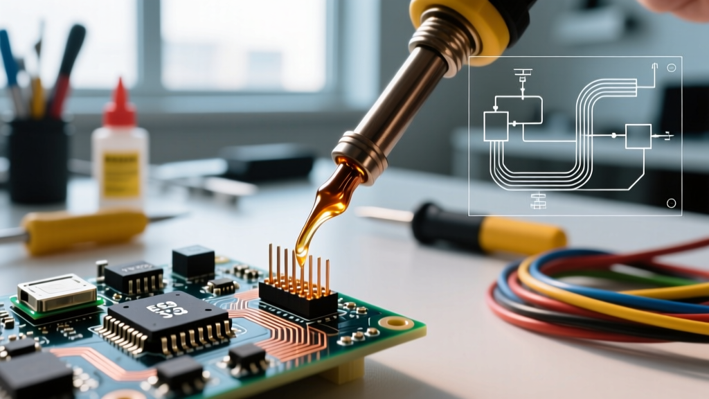
- Tin the Wire: Apply a tiny amount of flux to the exposed strands, touch your 350°C (662°F) iron to the wire, and feed in just enough 0.5mm solder to coat the strands. The wire should look shiny and cylindrical, not a bulky blob.
- Clean the FPCB Pads: Use a cotton swab dipped in 99% Isopropyl Alcohol (IPA) to remove any manufacturing oils or oxidation from the strip's copper pads.
- Flux the Pads: Dab a microscopic amount of tacky flux onto the copper pads on the LED strip.
Phase 2: The 3-Second Heat Rule
The adhesive bonding the copper layer to the polyimide FPCB substrate degrades rapidly above 200°C. Your goal is to complete the joint before the heat penetrates the board.
- Tin the Pad (Optional but recommended): Touch the iron to the strip's pad for 1 second to melt a tiny layer of solder onto it. Remove immediately.
- Join the Components: Hold the tinned wire flat against the tinned pad. Place the iron tip so it bridges both the wire and the pad simultaneously.
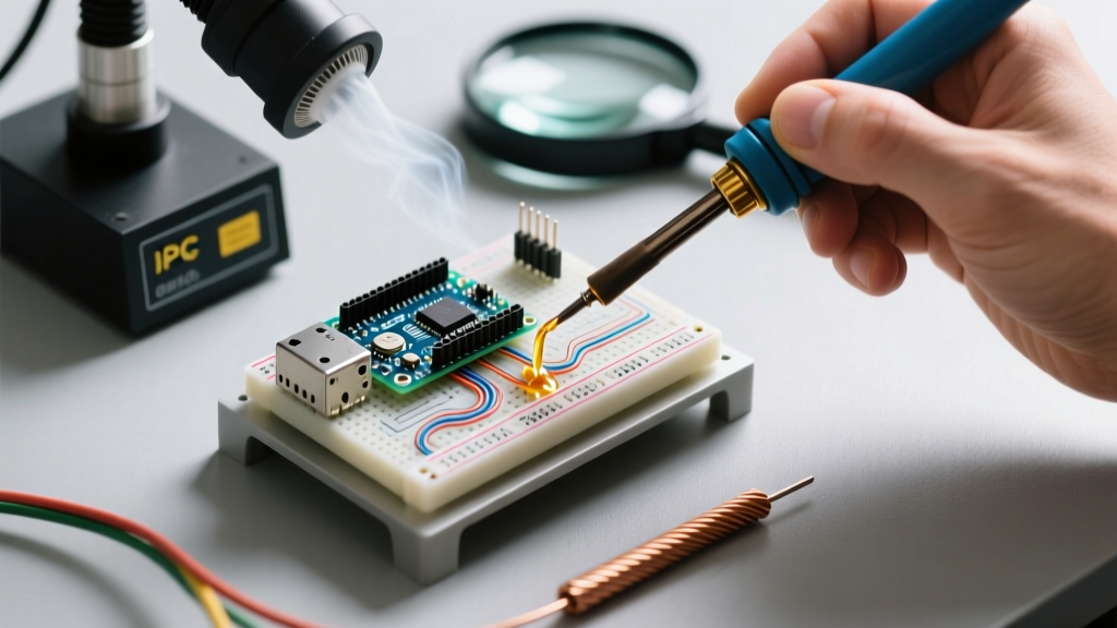
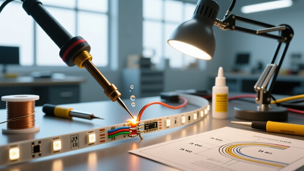
- Count to Three: Hold for a maximum of 2 to 3 seconds. You will see the solder flash and flow smoothly across the joint via capillary action. Remove the iron first, then hold the wire perfectly still for 2 seconds while the eutectic solder solidifies.
Pro Tip for Addressable Strips: When soldering the middle "Data In" (DIN) pad on a WS2812B strip, be exceptionally careful. Bridging this pad to the adjacent 5V pad will instantly destroy the first LED's internal logic IC upon power-up. Use a magnifying visor or a digital microscope to verify clearance before applying power.
Navigating IP65 and IP67 Silicone Coatings
Outdoor and bathroom installations require waterproof LED strips, which introduces a new hurdle: the silicone coating. IP65 strips feature a thin layer of silicone glue over the components, while IP67 strips are encased in a thick silicone sleeve.
- IP65 (Silicone Dot/Coating): Do not try to scrape the silicone off the copper pads with a knife; you will sever the micro-traces. Instead, use a fiberglass scratch pen or a specialized solvent to gently dissolve the coating directly over the end-pads.
- IP67 (Silicone Tube): Use a sharp hobby knife to slit the tube lengthwise about 2cm back from the end. Peel the tube back, expose the FPCB, and solder your wires. Once finished, slide the tube back over the joint and seal the entry point with a dab of neutral-cure silicone RTV sealant. Never use acidic bathroom caulk, as the off-gassing acetic acid will corrode the copper pads within weeks.
Common Failure Modes and Rework Strategies
Even seasoned DIYers encounter issues when soldering LED strip lights. Understanding how to diagnose and fix these edge cases is what separates novices from experts. For deeper insights into surface mount rework, the SparkFun SMD Soldering Tutorial provides excellent visual references for pad rescue.
1. Lifted or Delaminated Pads
The Cause: Holding the iron on the pad for more than 4 seconds, or using excessive downward pressure.
The Fix: If the +12V or +5V pad lifts, do not panic. Look closely at the FPCB and locate the nearest surface-mount resistor or capacitor connected to that trace. Scrape off a tiny bit of the solder mask from the trace leading to that component, apply flux, and solder a 24 AWG jumper wire from your main lead directly to that downstream component. You have effectively bypassed the broken pad.
2. The "Cold" or "Dull" Joint
The Cause: The iron wasn't hot enough, the wire moved during cooling, or insufficient flux was used. The solder looks grainy, dull, or ball-shaped rather than forming a smooth, shiny concave fillet.
The Fix: Do not just add more solder. Apply a fresh drop of liquid or tacky flux to the joint. Re-apply the iron for 2 seconds to allow the flux to clean the oxidation and let the solder reflow into a proper metallurgical bond.
3. Melted Plastic Connectors or Housings
The Cause: Using an iron temperature above 380°C (716°F) in an attempt to work faster, causing radiant heat to melt adjacent plastic lenses or connectors.
The Fix: Lower your station to 340°C-350°C. Rely on thermal mass and flux rather than raw temperature. A properly fluxed joint at 340°C will flow faster and cleaner than a dry joint at 400°C, while keeping the surrounding plastic components safely intact.
Final Verification and Power Testing
Before mounting your newly soldered LED strips behind aluminum extrusions or inside drywall coves, always perform a bench test. Connect the strips to your LED driver or microcontroller (such as an ESP32 for WLED setups) and run a full-spectrum white test, followed by a primary color cycle (Red, Green, Blue). This stresses the connections and reveals any hidden voltage drops or intermittent data faults while the strip is still accessible on your workbench. By prioritizing proper flux chemistry, precise temperature control, and correct wire gauges, your soldered LED installations will remain maintenance-free for years to come.