
The Baseline: Calibrating Your Approach to Soldering
Knowing how to use a soldering tool effectively extends far beyond simply melting metal onto a wire. It requires a deep understanding of metallurgy, thermal dynamics, and chemical flux reactions. Whether you are building a custom mechanical keyboard with a Pine64 Pinecil V2 ($28) or repairing heavy-gauge automotive wiring with a Weller WE1010NA ($135), the fundamental physics remain identical. However, the failure modes vary wildly based on your technique and equipment maintenance.
Before diving into troubleshooting, we must establish the thermal baseline for the two most common alloys you will encounter in 2026:
- Leaded Solder (Sn60/Pb40 or Sn63/Pb37): Melts at 183°C (361°F). Ideal iron tip temperature: 315°C to 350°C (600°F to 660°F). Best for hobbyists and rapid prototyping due to its wide plastic range and superior wetting.
- Lead-Free Solder (SAC305 - Sn96.5/Ag3.0/Cu0.5): Melts at 217°C (423°F). Ideal iron tip temperature: 350°C to 380°C (660°F to 715°F). Requires higher thermal mass and more aggressive flux activation to overcome the tin-oxide barrier.
Pro Tip: Never set your soldering station to maximum temperature to 'speed up' heating. Running a Hakko FX-888D at 450°C will oxidize the iron plating on your tip in under 10 minutes, permanently destroying its ability to transfer heat.
Troubleshooting Matrix: Diagnosing Solder Joint Failures
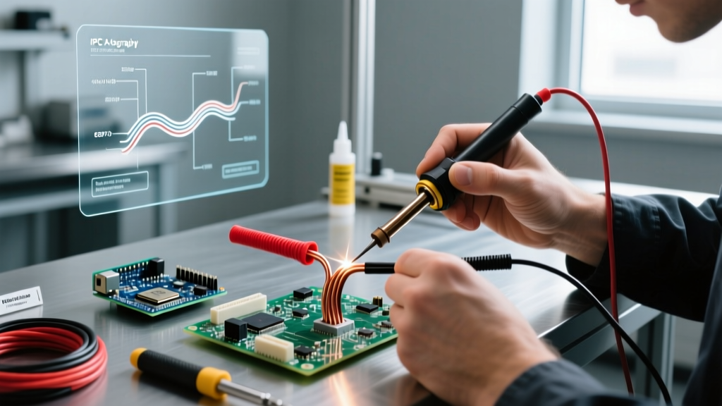
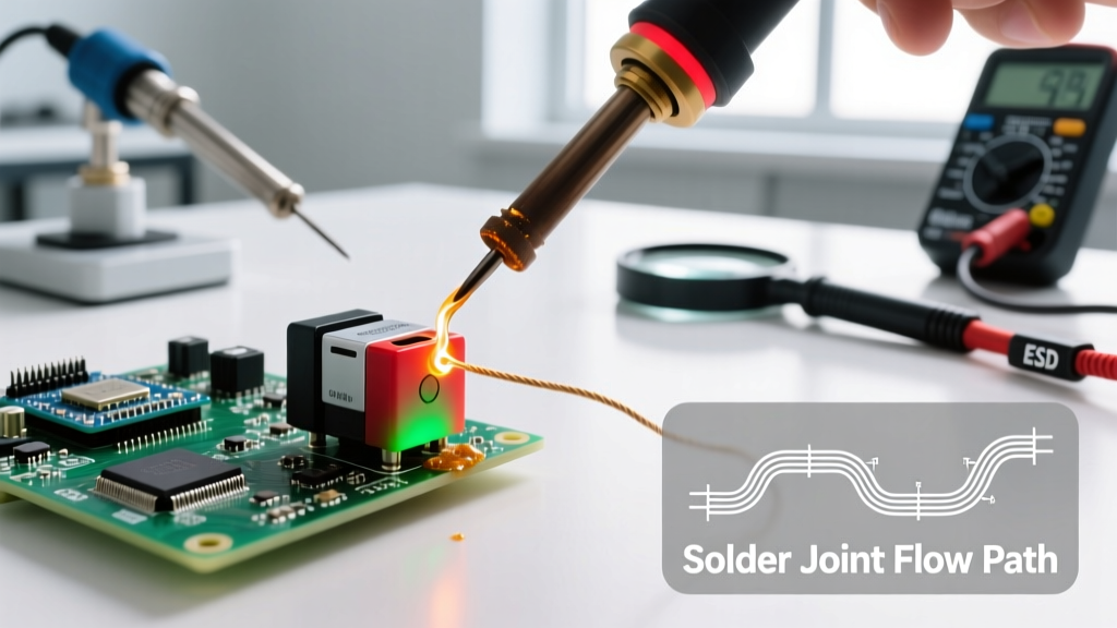
When learning how to use a soldering tool, you will inevitably create defective joints. The IPC-A-610 standard categorizes these defects into specific visual profiles. Use the matrix below to diagnose and correct your technique.
| Defect Type | Visual Cue | Root Cause | Actionable Fix |
|---|---|---|---|
| Cold Joint | Dull, gray, lumpy, or grainy surface; poor wetting to the pad. | Insufficient heat transfer; iron removed before solder reached liquidus phase. | Apply fresh mildly-activated rosin flux (e.g., Kester 186). Reheat the pad and lead simultaneously for 2-3 seconds until the solder flows like liquid glass. |
| Disturbed Joint | Frosty, cracked, or 'grainy' appearance with visible fault lines. | Component or wire moved during the critical liquidus-to-solidus phase transition. | Secure the component with a PCB vise or helping hands. Reheat fully and hold perfectly still until the solder solidifies (usually 1-2 seconds). |
| Dewetting | Solder pulls back from the edges, forming high contact angles (>90°). | Severe oxidation on the base metal or PCB pad; incompatible flux chemistry. | Clean the pad with isopropyl alcohol (99%). Apply a highly-activated flux or gently abrade the pad with a fiberglass scratch pen before re-tinning. |
| Solder Bridges | Unintended electrical connection between adjacent IC pins. | Excessive solder volume; incorrect tip geometry (using a massive chisel on 0.5mm pitch SMD). | Use a desoldering wick (Goot Wick CP-2060) with copious flux. Drag a clean, fluxed wick across the pins to absorb the excess via capillary action. |
| Overheated Pad | PCB pad lifts from the FR4 substrate; discoloration of the solder mask. | Dwell time exceeded 5 seconds; excessive tip temperature. | Allow the board to cool for 60 seconds. Use a lower-wattage iron for delicate SMD work, or apply a heat-sink clip to adjacent components. |
Frequently Asked Questions (FAQ)
Q: Why does my soldering iron tip turn black and stop melting solder?
A: This is the most common hurdle for beginners learning how to use a soldering tool. The black crust is iron oxide. The iron plating on modern tips (which protects the internal copper core from being dissolved by molten tin) oxidizes rapidly when exposed to air at temperatures above 350°C. Once oxidized, solder will not wet the tip, rendering it useless for heat transfer.
The Fix: Never use sandpaper or a file to clean a modern tip; you will expose the copper core, and it will dissolve into your solder within hours. Instead, use a brass wire sponge (like the Hakko 599B) while the tip is hot. If the oxidation is severe, use a specialized tip tinner (like Hakko FS-100), which contains abrasive powder and solder to chemically strip the oxide and re-tin the surface simultaneously.
Q: How do I choose the right wattage and tip geometry?
A: Wattage dictates thermal recovery, not maximum temperature. A 60W iron (like the Pinecil V2) can reach 400°C, but it will drop to 200°C the moment it touches a large ground plane, causing a cold joint.
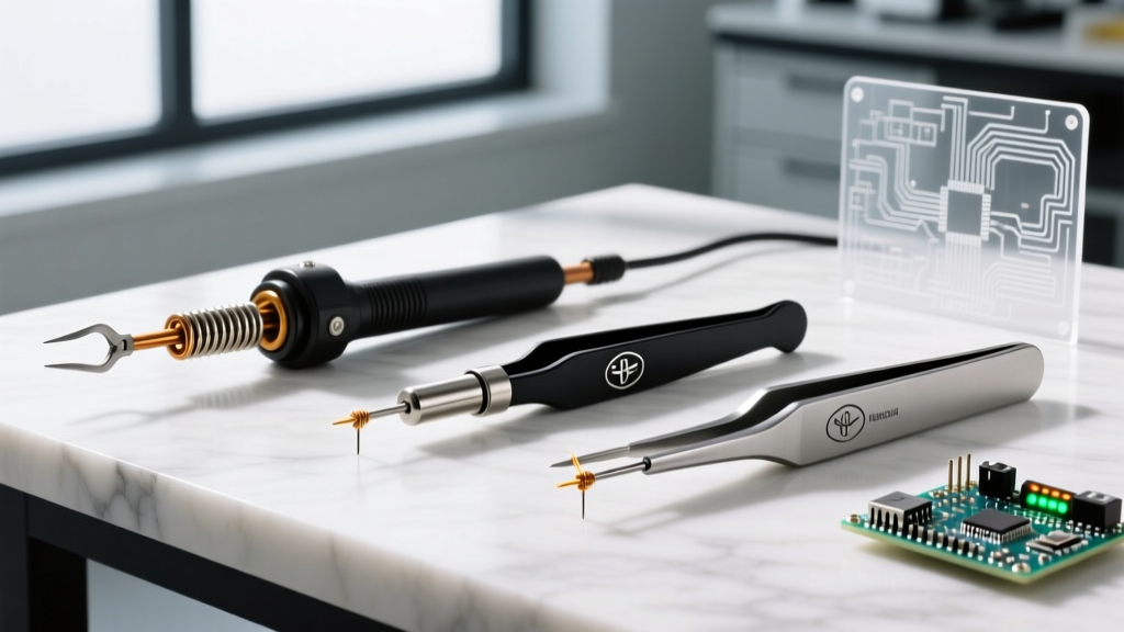
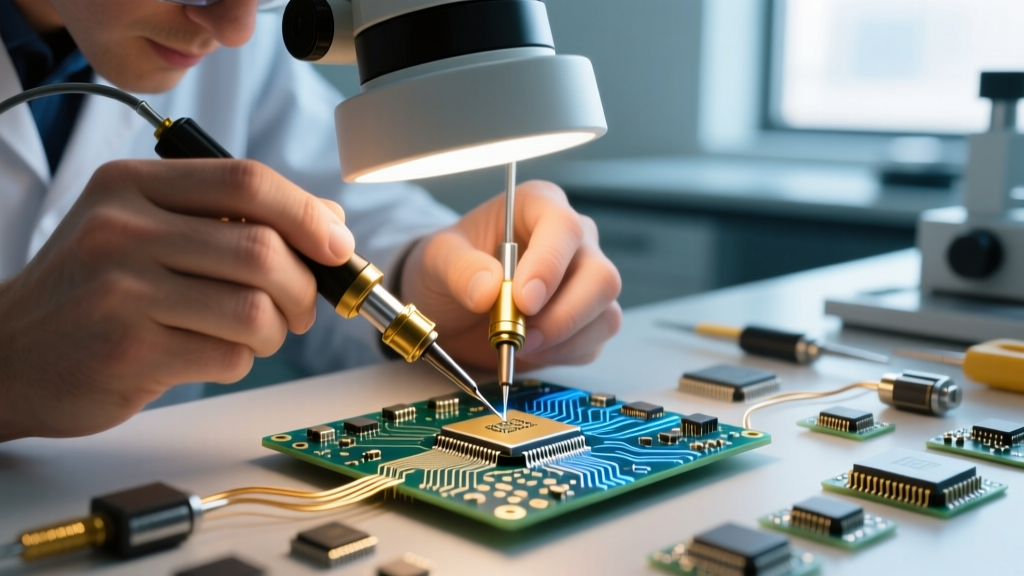
- For fine-pitch SMD and 0603 components: Use a 60W-70W station with a micro-pencil or fine conical tip (e.g., Hakko T18-I). This concentrates heat precisely without bridging adjacent pads.
- For standard through-hole and 18AWG wire: A 70W station with a standard chisel tip (e.g., Weller ETA) provides the best balance of surface area contact and thermal mass.
- For heavy ground planes and 10AWG+ wire: You need 100W+ (like the Weller WE1010NA or JBC CD-2BQE) and a massive bevel or hoof tip to maximize the contact surface area and pump joules of heat into the copper mass rapidly.
Q: Is a damp sponge or brass wool better for tip cleaning?
A: Brass wool is vastly superior for modern lead-free soldering. When you plunge a 380°C iron tip into a damp cellulose sponge, the rapid temperature drop (thermal shock) causes micro-cracks in the iron plating. Over time, molten solder penetrates these cracks, dissolves the copper core, and pits the tip. Brass wool cleans the oxidation mechanically without dropping the tip temperature, preserving thermal stability and tip longevity.
Advanced Edge Cases & Failure Modes
Even experienced technicians encounter anomalous failures. Here are two edge cases that frequently stump DIYers:
1. Galvanic Corrosion Post-Soldering
If you are using a water-soluble (Organic Acid / OA) flux like Kester 331 to achieve brilliant, shiny joints on stubborn connectors, you must clean the residue with distilled water or a specialized saponifier within hours. If left on the PCB, the highly active acids will cause galvanic corrosion, eating through the copper traces and creating high-resistance dendrites that cause intermittent short circuits. For general electronics where cleaning is difficult, always default to No-Clean (NC) or Rosin Mildly Activated (RMA) fluxes.
2. Thermocouple Degradation (Thermal Runaway)
If your soldering station's digital display reads 350°C, but the iron is either melting your PCB instantly or failing to melt solder, the internal thermocouple has likely degraded or the heating element ceramic has cracked. This is common in cheap, unbranded clones. The station's PID controller is receiving false feedback and overdriving the heating element. If recalibrating the station's offset menu (if available) fails, the handpiece must be replaced. Always invest in stations with replaceable handpieces and OEM sensor guarantees.
Maintenance Checklist for Longevity
To ensure your equipment lasts for years, integrate this checklist into your workflow:
- Pre-Heat: Turn the station on 3 minutes before use. Do not apply solder to a cold tip as it heats up; this causes uneven flux activation.
- Tinning Before Power-Off: Always leave a large blob of cheap, leaded solder on the tip before turning the station off. This sacrificial layer oxidizes instead of the tip's iron plating while it cools.
- Flux Management: Keep flux pens and paste jars tightly sealed. Volatile carriers evaporate quickly, turning paste flux into a hard, unusable puck.
- Cable Care: Do not wrap the silicone power cord tightly around the station or the iron handle. Repeated tight bending will fracture the internal thermocouple wires, leading to sensor errors.
Authoritative References
For further reading on industry-standard soldering requirements and defect classifications, consult the following authoritative resources:
- IPC Standards: The IPC-A-610 Acceptability of Electronic Assemblies remains the global benchmark for visual solder joint quality, detailing exact criteria for target, acceptable, and defective conditions.
- NASA Workmanship Standards: The NASA Electronic Parts and Packaging (NEPP) Program provides exhaustive, publicly available manuals (such as NASA-STD-8739.3) on high-reliability soldering techniques for aerospace applications.