
The Fallacy of the 'One-Size-Fits-All' Soldering Guide
Most tutorials on how to learn soldering begin with the same flawed premise: buy a generic $40 iron, grab some random wire, and start melting metal. This approach is the fastest way to lift a pad off a $500 drone flight controller or create a high-resistance joint that melts inside an automotive engine bay. Soldering is not merely 'gluing with metal'; it is applied metallurgy and thermal management.
To truly master this skill, you must first adopt a Decision Framework. The tools, alloys, and techniques required to build a mechanical keyboard are vastly different from those needed to repair a car's alternator wiring. This guide will help you identify your primary soldering domain, select the exact equipment required for 2026 standards, and execute the foundational skill acquisition protocol used by aerospace and consumer electronics technicians.
Phase 1: Define Your Soldering Domain
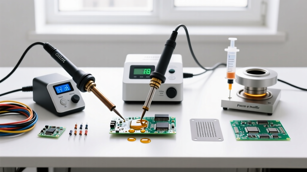
Before purchasing any equipment, you must define your end goal. The thermal mass of your target dictates your tool's wattage, while the operating environment dictates your solder alloy. Review the decision matrix below to find your primary domain.
| Soldering Domain | Primary Use Cases | Required Tool Type | Optimal Wattage / Temp | Recommended Alloy | Entry Budget |
|---|---|---|---|---|---|
| Micro-Electronics | PCBs, drones, audio gear, SMD | Smart Iron (T12 / USB-C) | 65W / 320°C (Leaded) | Sn63/Pb37 (Rosin Core) | $25 - $120 |
| Heavy Wire / Auto | Automotive, RC batteries, 10-14 AWG | High-Mass Station / Torch | 100W+ / 380°C | Sn60/Pb40 or Lead-Free | $90 - $250 |
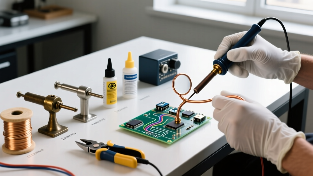
| Stained Glass / Jewelry | Copper foil, silver, structural | Rheostat-Controlled Iron | 100W - 200W / Variable | 60/40 Solid Wire + Paste | $100 - $300 |
Phase 2: Tool & Material Selection by Domain
Domain A: Micro-Electronics and PCB Repair
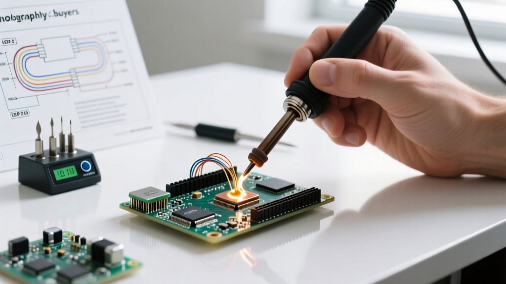
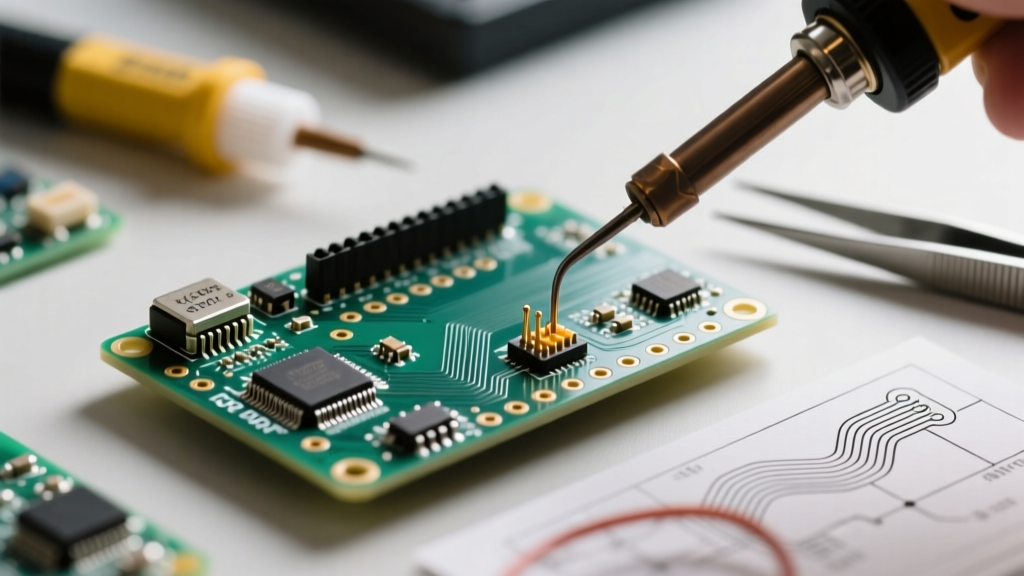
If your goal is working with printed circuit boards (PCBs), thermal precision and fast recovery are non-negotiable. Modern PCBs utilize heavy copper ground planes that act as heat sinks, pulling thermal energy away from your solder joint.
- The Smart Iron Choice: The Pine64 Pinecil V2 (approx. $26) has revolutionized entry-level electronics. Powered by USB-C (up to 65W via PD), it uses T12-compatible tips and features an onboard RISC-V chip that samples tip temperature multiple times per second, providing thermal recovery that rivals $200 bench stations.
- The Bench Station Choice: If you prefer a traditional grounded bench setup, the Hakko FX-888D (approx. $110) remains the industry workhorse. Its T18 tips offer excellent thermal mass for through-hole components.
- The Alloy: Use Sn63/Pb37 (63% Tin, 37% Lead). This is a eutectic alloy, meaning it transitions from solid to liquid at a single, precise temperature (183°C). It has no 'pasty' phase, which virtually eliminates cold joints caused by micro-movements during cooling.
- The Flux: Never rely solely on the rosin core inside your wire. Use a high-tack syringe flux like Amtech NC-559-V2-TF for SMD work, or a standard no-clean flux pen for through-hole.
Domain B: Heavy Gauge Wiring and Automotive
Soldering 10 AWG silicone wire for RC LiPo batteries or repairing automotive sensor harnesses requires brute thermal force. A standard 60W iron will suffer from catastrophic thermal droop the moment it touches thick copper.
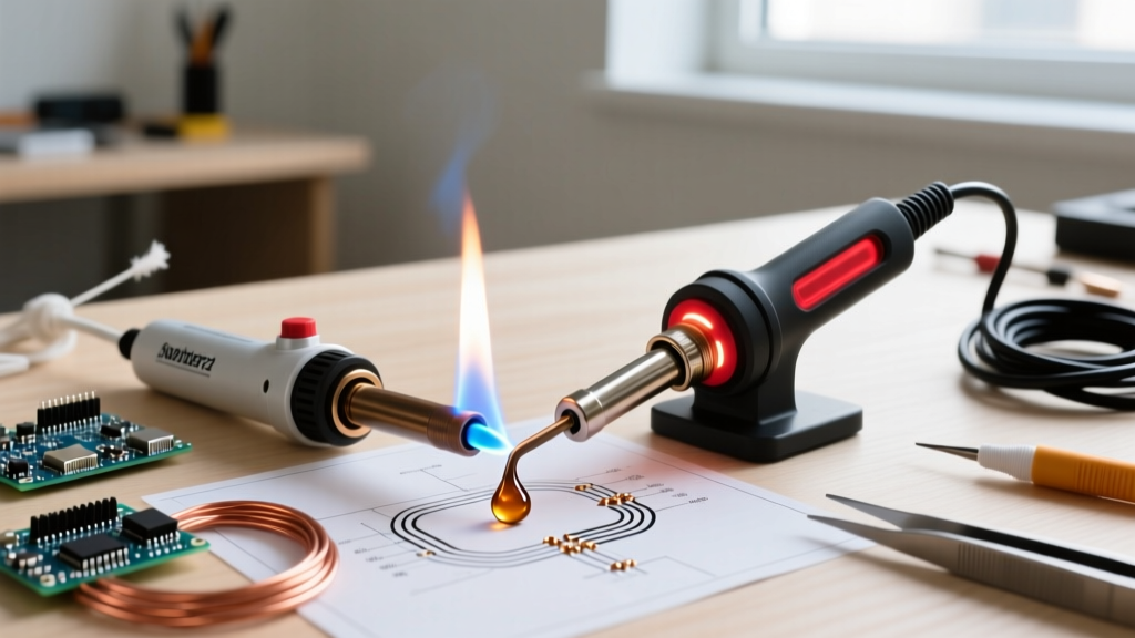
- The Tool: You need high thermal mass. The Weller W100PG (100W) or a high-quality butane torch (like the Blazer Big Shot) are required. For modern bench setups, a 200W station with a massive chisel tip (minimum 6mm width) is necessary to transfer heat into the wire core before the insulation melts.
- The Technique: Never solder automotive wires without a mechanical connection first. Use a Western Union splice or a crimp-and-solder hybrid approach. Solder is not a structural adhesive; it is an electrical bridge.
- Insulation: Always finish with dual-wall, adhesive-lined polyolefin heat shrink. The inner adhesive melts and seals out moisture, preventing the galvanic corrosion that destroys automotive solder joints.
Phase 3: The Metallurgy of Solder (Why Technique Matters)
Understanding why solder behaves the way it does is the secret to mastering how to learn soldering quickly. Many regions have mandated lead-free solders (like SAC305: 96.5% Sn, 3% Ag, 0.5% Cu) for commercial manufacturing due to environmental regulations. However, SAC305 is non-eutectic.
The Pasty Phase Danger: SAC305 begins to melt at 217°C but doesn't become fully liquid until roughly 220°C. In this 3-degree 'pasty' window, the solder looks solid but is structurally compromised. If a wire or component moves even a fraction of a millimeter during this cooling phase, the internal crystalline structure fractures, resulting in a 'disturbed joint' that will eventually fail under vibration.
Decision Point: Unless you are manufacturing commercial products for the EU market (RoHS compliance), always choose Sn63/Pb37 for hobbyist and repair work. It is vastly more forgiving, requires lower temperatures (saving your PCB pads and iron tips), and provides instant visual feedback via its bright, shiny finish.
Phase 4: The 4-Step Skill Acquisition Protocol
Forget making a perfect joint on the first try. Follow this deliberate practice protocol to build muscle memory.
- Step 1: Mechanical Preparation (The 80% Rule)
80% of a joint's strength comes from mechanical prep, not the solder. For wires, strip precisely 3/8" of insulation, twist the strands tightly, and tin them separately before joining. For PCBs, ensure component leads are bent to create physical tension against the pad. - Step 2: The 'Heat the Part, Not the Solder' Rule
Beginners touch solder to the iron, then dab the molten blob onto the wire. This is fundamentally wrong and causes cold joints. The correct sequence: Apply the iron tip to the pad and lead simultaneously. Wait 1.5 seconds for thermal equilibrium. Then, feed the solder wire into the joint, not the iron. If the part is hot enough, capillary action will instantly wick the solder into the joint. - Step 3: The 3-Second Limit
A standard through-hole joint should take no more than 2 to 3 seconds of heat application. If the solder hasn't flowed by second 3, remove the iron, let the board cool for 10 seconds, apply more flux, and try again. Prolonged heat will delaminate the copper pad from the FR-4 fiberglass substrate. - Step 4: Visual Inspection (IPC Standards)
Inspect your work against the IPC-A-610 Class 2 standards. A perfect solder joint should look like a smooth, concave volcano (a 'fillet') with a shiny surface. It should wet the entire pad and climb the component lead. Bulbous, dull, or lumpy joints indicate insufficient heat, lack of flux, or movement during cooling.
Phase 5: Troubleshooting Edge Cases & Failure Modes
Even with the right framework, you will encounter edge cases. Here is how to diagnose and fix the most common beginner failures.
1. The 'Thermal Relief' Ground Plane Problem
Symptom: You are soldering a capacitor to a ground pin, but the solder refuses to melt, or it forms a stubborn ball on the tip.
Cause: The PCB's internal copper ground plane is acting as a massive heat sink, drawing energy away faster than your 65W iron can supply it.
Solution: Do not turn your iron up to 400°C; this will oxidize your tip and burn the flux. Instead, use a PCB preheater (or even a modified coffee mug warmer set to 120°C) to raise the ambient temperature of the entire board. This reduces the thermal delta, allowing your iron to easily push the joint over the 183°C threshold.
2. The Blackened, Non-Stick Tip
Symptom: Solder rolls off the tip of your iron like water off a hot skillet.
Cause: Oxidation. Leaving an iron at 350°C while not in use causes the iron plating to react with oxygen, forming an insulating layer of iron oxide.
Solution: Never use sandpaper or a file on a modern iron tip; you will destroy the microscopic iron plating. Instead, use a brass wire sponge. For heavily oxidized tips, use a chemical 'Tip Tinner' (like MG Chemicals 4901). Dip the hot, blackened tip into the tinner paste for 3 seconds, then wipe on a damp cellulose sponge. The mild acid strips the oxide while the silver-tin alloy re-tins the surface instantly.
3. Solder Bridging on Fine-Pitch ICs
Symptom: Two adjacent pins on a microchip are connected by a blob of solder.
Cause: Surface tension failure due to lack of flux or excessive solder volume.
Solution: Add copious amounts of liquid or gel flux to the bridge. Take a clean, dry chisel tip and gently drag it across the pins. The flux will lower the surface tension, and the clean iron will absorb the excess solder via capillary action, pulling the bridge apart.
Final Thoughts on Deliberate Practice
Learning how to solder is not about memorizing a single technique; it is about understanding the thermal and chemical variables at play. By using this decision framework to match your tools to your specific domain, respecting the metallurgy of your chosen alloy, and adhering to strict mechanical preparation standards, you will bypass the frustrating 'trial and error' phase. Start with scrap through-hole PCBs or stranded wire offcuts, focus on the 3-second rule, and let capillary action do the heavy lifting.